


TDS2CMA Communications Module
146
TDS1000/2000-Series Digital Oscilloscope User Manual
The following procedure verifies communication with the oscillo-
scope by acquiring a signal and returning a voltage measurement.
This procedure assumes that the oscilloscope is connected to the
GPIB network, the oscilloscope has been assigned a unique bus
address, and that the controller software is running.
To test the GPIB interface, follow these steps:
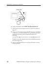
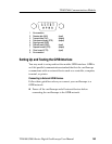
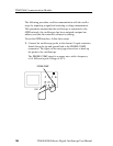
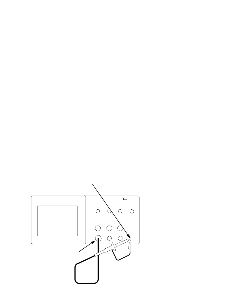
1. Connect the oscilloscope probe to the channel 1 input connector.
Attach the probe tip and ground lead to the PROBE COMP
connectors. The figure on the next page shows how to hook up
the probe to the oscilloscope.
The PROBE COMP signal is a square wave with a frequency
of ≈1 kHz and a peak voltage of ≈5V.
CH 1
PROBE COMP