


34
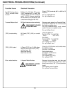
DISCONNECT POWER
FROM MACHINE !
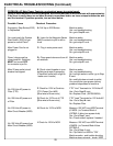
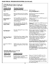
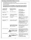
PROBLEM--Spin Drive not working in relief mode.
Assuming (SSS) System Start Switch is on with 120 volts AC to control panel and all other
functions are working.
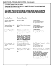
Verify all wires shown on the wiring diagram are correct and pull on wire terminals with
approximately 3 lbs force to verify there are no loose terminal connections and/or no
loose crimps between the wire and the terminal. If problem persists, test as listed below.
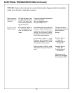
Possible Cause
Checkout Procedure
DISCONNECT POWER
FROM THE MACHINE
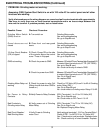
Relief Torque Pot
(RTP) set to zero.
Spin Motor Switch
(SMS) is not on.
Circuit Breaker is
Tripped (4 AMP)
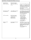
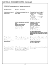
Spin Drive Control
(SDC) is not working
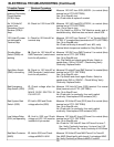
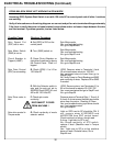
CB or Spin Motor Switch
(SMS) is bad
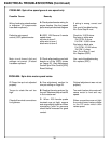
Spin Drive motor is bad
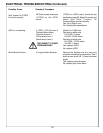
Worn Motor Brushes
Spin Motor works.
Yes--end troubleshooting
No--go to Step B. next
Spin Motor works.
Yes--end troubleshooting
No--go to Step C. next
Spin Motor works.
Yes--end troubleshooting
No--go to step D. next
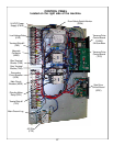
(SDC) Remove wires to Terminals
L1and L2 and test betwen wires for
120V AC.
Yes--reconnect wires, go to Step F.
No--Go to Step E. next
Remove Wire to SMS Terminal 6
"89SMS-6" and check between the wire
and nuetral (blue) terminal out of (FTR)
(02FTRBU) for 120 VAC
Yes--Check switch continuity, replace
No--Check CB continuity, replace.
Check for approx. 20 VDC from
Terminal Strip 1 Terminal 4 (48TB1-4)
to Terminal 5 (49TB1-5)
Yes--go to Step G. next
No--Go to Step I.
Remove motor wires at Terminal Strip 1
(left side lower strip), Term 4 & 5 and
check 0 ohms across the black and
white motor wires
Yes--end troubleshooting motor should
work (if it does not, replace motor)
No--go to Step H. next
Remove the brushes one at a time and
maintain orientation for reinsertion. See
if brush is worn short 3/8" (10 mm)
minimum length
Yes--replace motor brushes
No--replace Spin Drive Motor
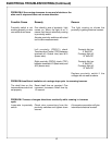
ELECTRICAL TROUBLESHOOTING (Continued)
A. Set (RTP) to 20 on the
control panel.
B. Turn (SMS) switch on.
C. Reset Circiut Breaker on
the right side of the machine.
Push in if tripped.
D. Check (SDC) L1 to L2 for
120 Volts AC
E. Check power into (SMS)
terminal 6 for 120 Volts AC
F. Check (SDC) A1 & A2 for
approx. 20 Volts DC (Have
Relief Torque set to maximum
torque - full clockwise.
G. Check spin motor continuity
H. Inspect Motor Brushes