


13
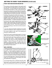
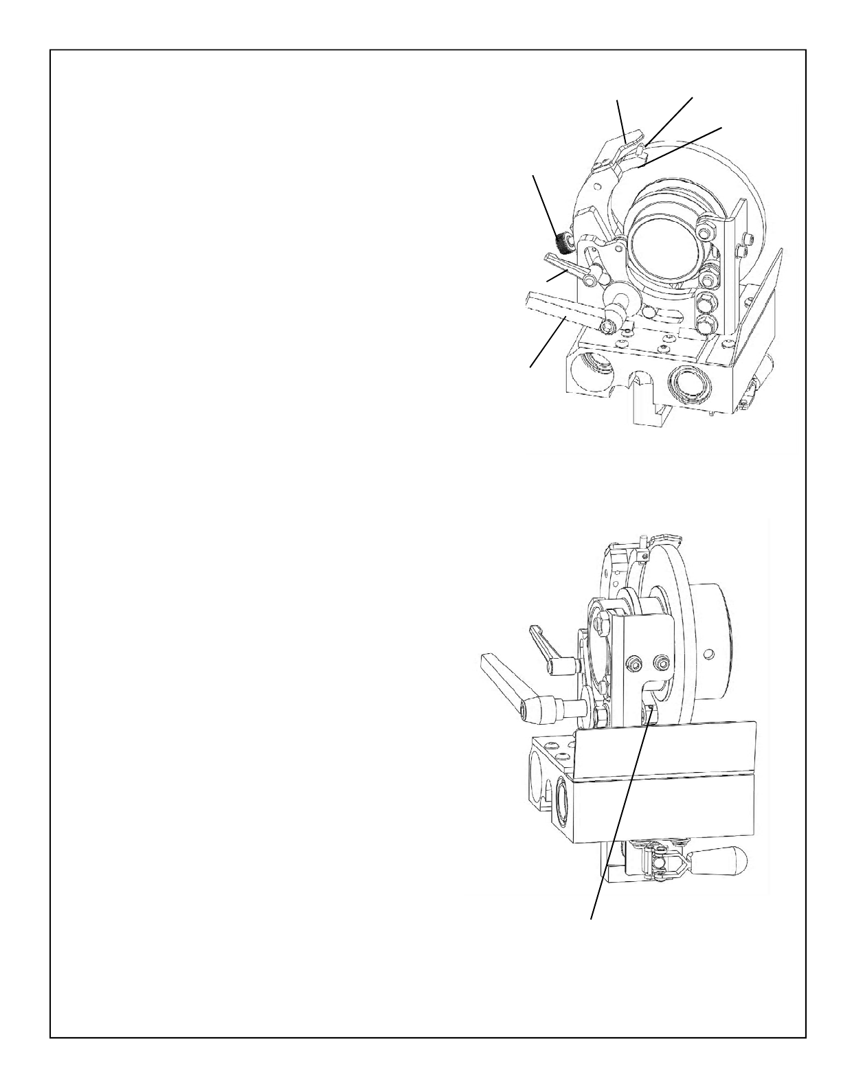
FIG. 6
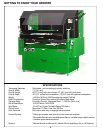
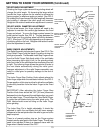
GETTING TO KNOW YOUR GRINDER (Continued)
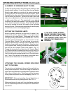
INDEX FINGER ADJUSTMENTS
The Relief Assembly includes two fingers. See FIG. 6. The
Fixed Relief Finger hold the blade in position during the
relief grind process. The Movable Index Stop Finger moves
from the Relief Finger Side (back side) of the reel blade
when traversing from right to left, to the grinding wheel
side (front side) of the reel blade when traversing from left
to right. The indexing finger allows the grinder to index to
the next blade automatically during the relief grind.
Improper adjustment of the relief fingers assembly may
result in a bad grind or possibly damage to the reel or
machine.
The Index Finger Stop Position Knob adjusts where the
Index finger stops when the reel blade indexes. See FIG. 6.
Proper position of this stop is critical to allow the reel blade
to smoothly transition from the Index Finger to the Fixed
Finger.
IMPORTANT! After adjusting the Index Finger Stop
Position Knob there should be 1/32" [0.8 mm] clearance
between the index finger and the reel blade when you push
on the index finger. This will allow the Fixed Relief Finger
to guide the reel blade during the relief grind cycle. The
Reel blade should never be riding on the Index Finger
when grinding.
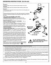
The Index Stop Pin is height adjustable. It should be
adjusted to catch the reel blade and still leave enough
clearance to the reel spider after the relief is ground to the
depth required.
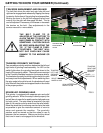
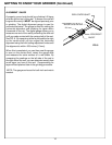
There is a forward position stop on the Finger system
located near the pivot point of the Index Finger. This will only
need to be adjusted if there is a clearance issue with the
finger when it travels forward. See FIG 7.
RELIEF ANGLE ADJUSTMENT
Rotating the finger system around the grinding wheel will
change the relief angle. By loosening the large ratchet
handle the finger system can be rotated to achieve the
factory angles, or whatever angle you select. See FIG. 6.
By rotating the finger forward the relief angle will decrease
and rotating it rearward the relief angle will increase.
Retighten the ratchet handle when adjustment is correct.
RELIEF WHEEL DIAMETER ADJUSTMENT
As the wheel wears, the finger system will need to be
adjusted to maintain the correct gap between the fixed
finger and wheel. To move the finger system loosen the
small ratchet handle. See FIG. 6. The gap between the
fixed finger and the grinding wheel should be between
.06" [1.5 mm] and .18" [4.6 mm] depending on the amount
of existing relief on the reel. Retighten the ratchet handle
after the adjustment is made.
RELIEF ANGLE
ADJUSTMENT
HANDLE
WHEEL DIAMETER
ADJUSTMENT
HANDLE
INDEX FINGER
STOP POSITION
KNOB
FIXED FINGER
MOVABLE
INDEXING
FINGER
INDEX STOP
PIN
INDEX FINGER
FORWARD STOP
POSITION
SETSCREW
FIG. 7