


18
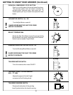
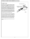
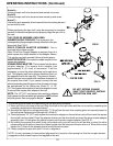
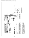
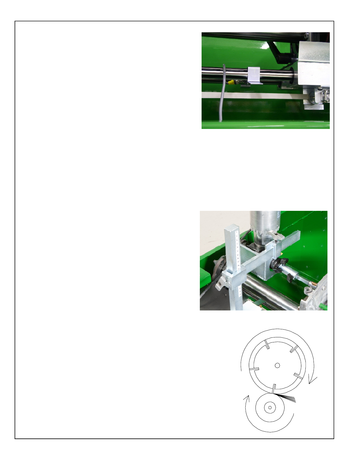
ATTACHING THE VARIABLE SPEED SPIN DRIVE
UNIT TO THE REEL
The spin drive unit attaches to the end of the reel shaft or a
drive system component. Consult the cutting unit manual for
proper spin drive placement and attachment. Determine which
side to mount the spin drive. This will generally be the same
drive system component used for backlapping. See FIG. 18.
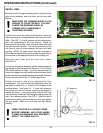
IMPORTANT: When spin grinding, the reel should turn in
the same direction as the grinding wheel. See FIG. 19.
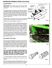
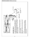
Before positioning the spin unit let us familiarize ourselves
with the available adjustments and coupler/drive assemblies.
See FIG. 20.
FIG. 18
FIG.19
OPERATING INSTRUCTIONS (Continued)
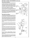
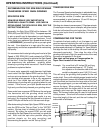
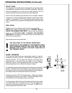
ALIGNMENT OF GRINDING SHAFT TO REEL
To align the grinding shaft to the reel bring the shaft up so that
the spin wheel is about ¼ inch [6 mm] from the reel blades.
Move the spin wheel to one side of the reel and raise the
grinding shaft until the wheel just touches the blade. Move
the wheel to the other side of the reel and bring the shaft up
until the wheel just touches. Recheck from side to side and
make minor adjustments until the wheel touches the same
on both ends of the reel. The grind shaft is now aligned
vertically to the reels outer diameter. Zero the gauges located
on the vertical adjustment housing. Check for high spots in
the reel by moving the wheel the length of the reel while
spinning the reel. If there are high spots lower the shaft equally
on both ends and zero out the gauges again.
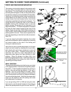
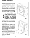
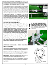
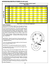
SETTING THE TRAVERSE LIMITS
Move the grinding wheel to the right until the wheel has
cleared the reel by approximately ¼ inch [6 mm] (if
clearance to the frame allows). Disengage both the relief
and Spin grinding assemblies from traverse belt. Turn the
Traverse speed potentiometer to zero and turn on the
Traverse Motor Switch. This will activate the proximity
sensors. Move the right Traverse Travel Limit switch in until
the light on the proximity sensor illuminates. Move the wheel
to the opposite end, clearing the reel as mentioned above,
and set the left Traverse Travel Limit Switch. (Fig 17)
Engage the traverse belt and slowly turn the Traverse Speed
up. Allow the wheel to traverse from end to end to verify the
switches stop and reverse the direction of the grinding wheel.
Verify that the grinding wheel travels fully off the reel at each
end. Note: If the reel will hit the frame, then adjust travel
sensors so the wheel does not contact the frame.
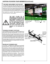
IF THE REEL FRAME EXTENDS
BELOW THE REEL ITSELF, MAKE
SURE THE STOP IS SET SO THAT
THE GRINDING WHEEL DOES NOT
RUN INTO THE FRAME WHILE
GRINDING.
!
FIG. 17