


29
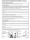
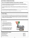
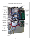
ELECTRICAL TROUBLESHOOTING (Continued)
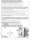
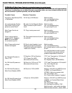
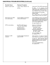
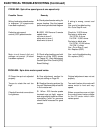
Checkout Procedure
No 120 Volts AC
power to Secondary
Circuit Breaker
(SCB) 6 Amp.
No 120 Volts AC
power from
Secondary Circuit
Breaker (SCB) 6
Amp.
120 Volts AC power
not delivered to
Terminal Strip
Grinding Motor
Switch (GMS) not
working
Spin Motor Switch
(SMS) not working
Bad Emergency
Stop Switch (ESS)
Bad System Start
Switch (SSS)
Low Voltage Relay
(REL) not operating
Bad Main Contactor
(MAG)
Possible Causes
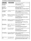
J. Check for 120V to SCB
K. Check for 120V from SCB
L. Check for 120 Volts AC at
terminal strip.
M. Check for 120 Volts AC at
GMS Terminals 1 (switch must
be in the off position)
N. Check for 120 Volts AC at
SMS Terminals 1 (switch must
be in the off position)
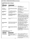
O. Check voltage after the
(ESS)
MAKE SURE SWITCH IS
PULLED UP!
P. Hold in SSS and Check
voltage after the (SSS)
Q. Hold in SSS and Check
voltage at LVR. LVR must be
installed in 8-pin socket.
R. Hold in SSS and Check
voltage at MAG A1 & A2.
Measure 120 VAC from SCB (03SCB--) to nuetral (blue)
terminal out of FTR (02FTRBU)
Yes--Go to Step K. next.
No--Check wires & replace if needed.
Measure 120 VAC fromSCB (67SCB--) to nuetral (blue)
terminal out of FTR (02FTRBU)
Yes-- Go to Step L. next.
No--Flip Switch on SCB to "ON"-Machine works--end of
troubleshooting. Machine does not work--check SCB
Measure 120 VAC from Terminal "11" on Terminal Strip 2
"07TB2-11" to nuetral (blue) terminal out of FTR (02FTRBU)
Yes--Go to Step M. next.
No--Check continuity of wires #07 and #03, verify
terminal block Jumper are installed on Grey Blocks 1-3.
Measure 120 VAC from GMS Terminal 1 to nuetral (blue)
terminal out of FTR (02FTRBU)
Yes--Go to Step N. next.
No--Flip Switch and check again-Works--Switch is
upside down. Still no 120VAC-- Check wiring/Verify
Continuity/ Replace Switch
Measure 120 volts AC from SMS Terminal 1 to nuetral (blue)
terminal out of FTR (02FTRBU)
Yes--Go to Step O. next.
No--Flip Switch and check again-Works--Switch is
upside down. Still no 120VAC -- Check Wiring/ Verify
Continuity/ Replace Switch
Measure 120 Volts AC from (ESS) terminal 2 to nuetral
(blue) terminal out of FTR (02FTRBU)
Yes--Go to Step P. next
No--Check wire for continuity, then verify switch
continuity. If bad replace ESS contactor (NC)
Measure 120 Volts AC from (SSS) term 3 to nuetral (blue)
terminal out of FTR (02FTRBU)
Yes--Go to Step Q. next
No--Check wire for continuity, then verify switch
continuity. If bad replace SSS contactor (NO)
Measure 120 Volts AC from LVR term 8 to nuetral (blue)
terminal out of FTR (02FTRBU)
Yes--Go to Step R. next
No--Check for 120 Volts AC from LVR term 6 to term 7.
Yes--Verify Continuity from term 1 to term 8 on LVR.
Replace LVR if bad. No--Verify Continuity of LVR Wires.
Measure 120 Volts AC from MAG Term A1 to Term A2
Yes--MAG Should pull in with clunck, if not replace MAG.
No--Verify Continuity of Wires to MAG A1 and A2