


16
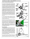
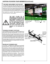
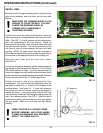
INSTALL REEL
Move the reel to the approximate position having the rear
roller on the tabletop, and front roller on the front roller
Mounts.
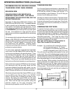
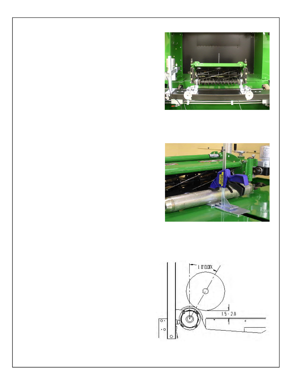
Position front reel in the center of the machine. Move the
roller mounts as far out as possible to the ends of the front
roller. (See FIG 11). Use the decals on the tooling bar to
aid in the positioning of the front tooling. Check for
clearance to the tooling, front roller and frame with both
the spin and relief wheels. This will ensure that you will
not have to move the reel between the spin and relief
grinding. NOTE: On large reels it may be necessary to
offset the reel slightly from center to allow the spin drive to
be mounted on the appropriate side of the cutting unit.
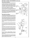
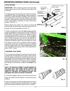
Place the rear roller onto the rear roller clamp.
(See FIG 12).
If using the all-position brackets, set the vertical height of
the clamps so that the bottom of the reel is 1.5-2.0 inches
[38-51mm] above the table. It is also recommended to
mount the support arm with as little extension from the all
position bracket as possible leaving just enough clearance
for mounting the reel in the “V” of the support arm.
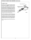
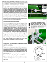
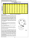
Position the reel in and out by adjusting the front
handwheels. The reel should be positioned so that the
reel shaft is located at a 1 o’clock or 30° position to the
grinding wheel. See figure 13. If there are clearance
issues the reel can be moved forward or backward to
resolve this issue. If you are grinding a QA5 or QA7 reel
use the decals located on the tooling to quickly locate the
reel in the optimal position. See FIG 2. After the reel is
positioned correctly lock down the front roller and tighten
the rear clamp. Make sure all knobs are tight before
grinding.
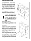
OPERATING INSTRUCTIONS (Continued)
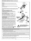
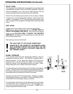
MAKE SURE THE GRINDING WHEEL IS LOW
ENOUGH TO CLEAR THE REEL. YOU CAN
LOWER THE GRINDING WHEEL BY
TURNING BOTH HANDWHEELS
COUNTERCLOCKWISE.
FIRMLY TIGHTEN ALL LOCKING KNOBS
BEFORE GRINDING. ANY LOOSE KNOBS,
CLAMPS OR BEARINGS WILL ADVERSELY
AFFECT THE GRIND QUALITY.
FIG. 11
30° angle or
FIG. 12
FIG. 13
!
!