


26
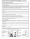
This Electrical Troubleshooting section is designed for technicians who have the necessary electrical
knowledge and skills to reliably test and repair the RG5500 electrical system. For those without that background,
service can be arranged through your local dealer.
This section presumes that you are already familiar with the normal operation of the Grinder. If not, you
should read the Operator's Manual, or do the servicing in conjunction with someone who is familiar with its
operation.
Persons without the necessary knowledge and skills should not remove the control panel cover or attempt
any internal troubleshooting, adjustments, or parts replacement.
If you have any question not answered in this manual, please call your local dealer.
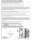
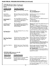
AC Main Power Controls ...................................................................................................Page 28-30
Grinding Motor Controls ....................................................................................................Page 31
Spin Drive Controls ...........................................................................................................Page 32-36
Traverse Drive Controls ....................................................................................................Page 37-41
Mechanical Troublshooting ................................................................................................Page 42-43
ELECTRICAL TROUBLESHOOTING
SKILL AND TRAINING REQUIRED FOR ELECTRICAL SERVICING
TROUBLESHOOTING INDEX
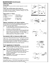
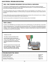
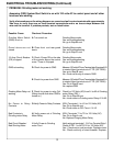
All wires on the RG5500 have a wire label at each end for troubleshooting. The wire label has a code which
tells you wiring information. The wire label has a seven position code. The first two or three digits are the wire
number: 01-199. The next three numbers or letters are the code for the component to which the wire attaches.
Example: TDC for Traverse Drive Control. The last two numbers or letters are the number of the terminal on
the component to which the wire attaches.
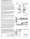
WIRE LABELS
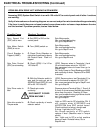
TERMINAL BLOCKS:
To insert or remove a wire from the
terminal block insert a small screw
driver into the square hole. Then insert
or remove wire from the round hole.
Remove screwdriver to lock the wire in
place.
Note the square hole can also be used
when checking for voltages. The probe
tip of the multimeter can be inserted
into the square hole to take readings.