


31
ELECTRICAL TROUBLESHOOTING (Continued)
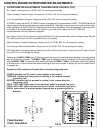
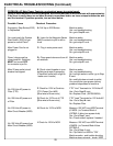
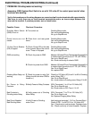
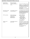
PROBLEM-- Grinding motor not working.
Assuming (SSS) System Start Switch is on with 120 volts AC to control panel and all other
functions are working.
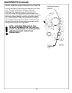
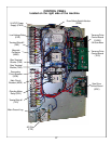
Verify all wires shown on the wiring diagram are correct and pull on wire terminals with approximately
3lbs force to verify there are no loose terminal connections and/or no loose crimps between the
wire and the terminal. If problem persists, test as listed below.
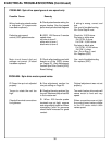
Possible Cause
Grinding Motor Switch
(GMS) is not on
Guard doors are not
closed
15 Amp Circuit Breaker
(CB) is tripped
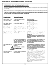
GMS not working
Grinding Motor Relay not
working
No Power to Relay
Contacts
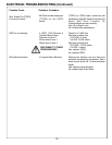
Bad Contacts in
Grinding motor Relay
Bad Circuit Breaker/
Bad Grinding Motor
Checkout Procedure
A. Turn switch on
B. Close front and rear guard
doors
C. Check 15 amp CB on the side
of the grinder above the control
cover. Press in if tripped.
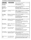
D. Check for power to GMS
E. Check for power from GMS
F. Check for power to relay Coil
(Relay should click when GMS is
turned on.)
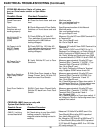
G. Verify Power to Relay Contacts
H. Verify power out of Grinding
Motor Relay.
I. Verify Power to Grinding
motor Cord.
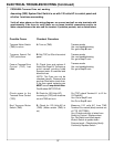
Grinding Motor works
Yes--end troubleshooting
No--go to Step B. next
Grinding Motor works
Yes--end troubleshooting
No--go to Step C. next
Grinding Motor works
Yes--end troubleshooting
No--go to Step D. next
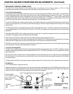
Measure 120 volts AC from Terminal strip 2 terminal #15
to nuetral (blue) terminal out of FTR (02FTRBU)
Yes--go to Step E. next
No-- check continuity of wires to GMS.
Measure 120 volts AC fromT erminal strip 2 terminal #14
to nuetral (blue) terminal out of FTR (02FTRBU)
Yes--Go to Step F. next
No--replace GMS
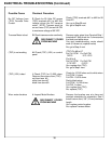
Check for 120 Volts (AC) from A1 to A2 of Grinding
motor Relay (REL)
Yes--Go to Step G. next
No-- check wires to Grinding motor Relay A1 & A2.
(REL) Terminals L1 to L2 for 120 Volts (AC)
Yes--Go to Step H. next
No--Check wires to REL Term L1 & L2
(REL) Terminals T1 to T2 for 120 Volts (AC)
Yes--Go to Step I. next
No--Replace Gringing Motor Relay
Verify wiring at terminals 1, 2 & 3 on Terminal Strip 1.
Check 42TB1-1 to 64TB1-2 for 120 Volts (AC).
Yes-- Check motor cord terminals. Replace motor.
No-- Check continuity of circuit breaker. Replace.