


19
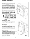
OPERATING INSTRUCTIONS (Continued)
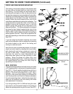
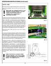
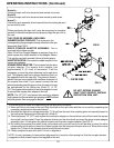
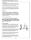
Knob A—
Allows the spin unit to be loosened and moved in and out.
Knob B-
Allows the spin unit to be loosened and moved up and down.
Knob C –
Allows the spin assembly to be loosened from the tooling bar and
moved side-to-side.
When positioning the spin unit it may be necessary to complete
several of the above adjustments to properly align the spin unit to
the reel.
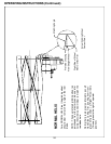
FIG.20
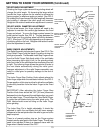
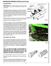
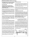
THE COUPLER ASSEMBLY INCLUDES:
RUBBER SLEEVE COUPLER: This is placed in the
corresponding flange coupler already mounted in the spin
drive shaft. See FIG. 21.
DRIVE COUPLER ADAPTER ASSEMBLY: This is
mounted to the rubber coupler.
Note: If the Drive Coupler Adapter is removed, there is a
short square drive shaft attached to the Adapter Sleeve.
This can be used with a socket if there is limited space.
ADAPTER SLEEVE: Connects the rubber coupler to the
square drive adapter.
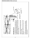
SQUARE DRIVE ADAPTER: This is inserted into the drive
coupler adapter. The square drive adapter has
approximately 2" [51 mm] of movement. It will be
necessary to move this when attaching reel to spin drive
unit. This adapter shaft has a groove machined into it on
the opposite end of the snap ring. This groove is there to
advise that you have reached the maximum extension of
the square drive shaft. If you cannot connect the reel
without extending past this groove, then the spin unit must
be repositioned on the tooling bar (Knob C). A 1/2"
[12.7 mm] square drive socket or reel drive adapter is used
to connect the square drive adapter to the reel.
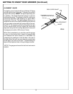
FIG. 21
DO NOT EXTEND SQUARE
SHAFT PAST GROOVE, INSTEAD
REPOSITION SPIN UNIT.
NOTE: The 1/2" [12.7 mm] square drive socket or adapter
that is placed on the reel when spin grinding is NOT
included
with the grinder. See next page for details
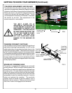
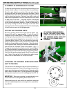
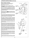
The following procedures will make setting up the spin drive unit easier.
1.
2.
3.
4.
5.
Move spin drive unit close to the reel. Align the shaft on the spin drive with the nut on reel by completing the
necessary adjustments discussed above.
Now slide the spin drive unit approximately 7" [18 cm] from the reel drive coupling point and securely fasten to
the tooling bar tightening the locking knob. (Knob C)
Place the proper 1/2" [12.7 mm] square drive socket or adapter on the reel drive nut and then insert the square
drive shaft into the socket. Place the adapter sleeve over the drive shaft and insert the drive coupler adapter
assembly into it. Finally place the rubber coupler onto the drive coupler adapter. See FIG. 21.
By holding the square drive shaft firmly into position with your left hand you will be able to move the other
components to the right and insert the rubber coupler into the flange on the spin drive unit. When this is done
tighten the T-Knob on the adapter sleeve to hold all parts in place.
Finally readjust the spin drive unit if it is not in alignment.
NOTE: It is not necessary to have perfect alignment but it must be close enough so that the coupler remains
engaged and that excess torque is not applied to the reel.