


17
OPERATING INSTRUCTIONS (Continued)
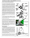
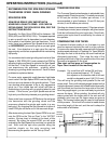
ALIGN THE REEL
IMPORTANT: When measuring to the reel center shaft
always make sure you are contacting an area free of dirt
and grass.
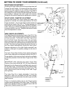
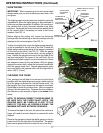
The digital gauge horizontal extension bracket is vertically
adjustable to allow the digital gauge to be positioned to
avoid any reel frame member. In addition, the mounting of
the vertical slide to the horizontal weldment has three
positions. Removed the knob on the side to adjust the tilt
of the vertical slide if necessary to avoid a reel frame
member. See FIG. 14.
Before aligning the cutting unit, loosen the horizontal
locking knobs on the tooling, to allow the cutting unit to be
adjusted in the horizontal plane. See FIG. 14.
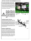
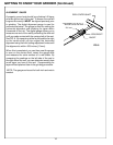
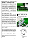
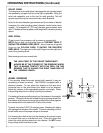
To align the cutting unit, move the digital gauge assembly
as far as possible to the left side of the reel. Extend the
digital gauge making sure the tip of the gauge is centered
on the reel center shaft. See FIG 15. With the gauge
pressed against the reel center shaft, set the gauge to
zero. Retract the gauge and move to the right side of the
reel and measure to the center of the reel shaft. Do not
rotate the reel shaft except for a minimum amount if there
are clearance issues to the reel blades. With the gauge
against the center shaft, adjust the horizontal handwheel
until the gauge reads zero. Repeat adjustments going
from one side to the opposite side until the alignment is
within .005" [.13 mm].
FIG. 15
FIG. 14
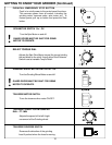
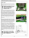
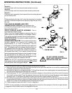
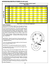
CHECKING FOR TAPER
First, measure the left side of the reel as far to the left as
possible with the digital alignment gauge, make sure the
tip of the gauge is centered on the reel center shaft. Set
the gauge to zero, then measure to the edge of one blade.
Remember or write this number down. Move to opposite
side and do the same thing. Compare the two numbers;
the difference is the amount of taper in the radius of the
wheel.
NOTE: TO OBTAIN A CORRECT TAPER READING TO
BE USED WITH THE TAPER CHART LATER, THE
READING MUST BE TAKEN AS CLOSE TO THE
ENDS OF THE REEL AS POSSIBLE GIVING THE
MAXIMUM DISTANCE BETWEEN READINGS.
To remove the taper in the reel, the side of the reel that is
larger will need to be infed heavier to remove this extra
material.
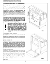
Remove the gauge and store the digital gauge on the pin
located on the front right side of the machine. The gauge
base can be placed inside the machine out of the way.
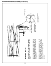
FIG. 16
GAUGE ANGLE
ADJUSTMENT
T-KNOB
GAUGE VERTICAL ADJUST-
MENT T-KNOB
HORIZONTAL
ADJUSTMENT
HANDWHEEL
GAUGE
BASE
FORWARD AND
BACKWARD
MOUNTING HOLES
TOOLING BAR
POSITION KNOB
HORIZONTAL
LOCKING T-KNOB