


22
ADJUSTMENTS (Continued)
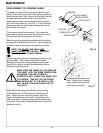
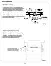
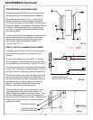
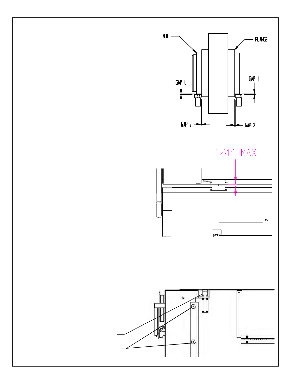
SPIN GRINDING HEAD WEAR PADS
The bronze wear pads used to move the spin wheel
will wear and may need to be adjusted or replaced.
When pad wears to within a 1/16" [1.5 mm] of the
screws, the pad will need to be flipped or replaced.
The holes in the pads are offset slightly, this allows the
pads to be flipped if neccessary to accomplish the best
fit. When installing new pads, flip or rotate the pads
until Gap 2 is as small as possible without the pads
pinching the wheel.
On the spin grinding head assembly, the distance from
the pad to the wheel can be adjusted in and out by
loosening the screws located on the sides of the
yokes. Gap 1 should be adjusted to about 1/16"
[1.5 mm]. See FIG. 19
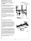
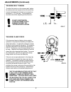
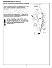
SAFETY SWITCH ALIGNMENT/REPLACEMENT
The safety switch located on the front and rear guard
door must line up properly or the grinder will not
function.
The front door switches must be within 1/4" [6 mm]
and the targets on the switches must line up in order
for the switch to function properly. See FIG. 20 and 21.
The switches and the key are attached to the guarding
using a "Torx" style tamper resistant screws. A tool for
this type of screw is required to make this adjustment.
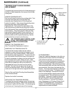
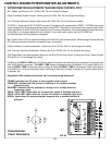
The rear door switch may need to be adjusted so that
the key slides smoothly into the door safety switch. If
the switch and key do not align, loosen the screws on
the switch or key housing and adjust until they are
aligned. Then tighten all screws and check the
function of the rear door and door switch.
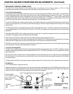
If the door has too much side to side play, this may
cause alignment issues with the door switch. To
adjust, loosen the screws that hold door slides. Then
push the slides toward the center of the machine to
remove any side to side play in the door. Retighten the
screws and test then door until the key consistently
engages the switch.
FIG. 19
FIG. 20
REAR DOOR SWITCH
FRONT DOOR SWITCH
(INSIDE UPPER RIGHT SIDE)
FIG. 21
DOOR SLIDE SCREWS
(THERE ARE 6 PER SIDE)