


12
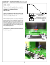
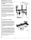
FIG. 6
APPLY POWER
BEFORE YOU APPLY POWER TO THE GRINDER,
REFER TO THE "IMPORTANT GROUNDING
INSTRUCTIONS" ON PREVIOUS PAGE.
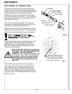
Plug the control box power cord into a standard 115V AC 20-amp
grounded receptacle. See FIG. 6.
IT IS RECOMMENDED THAT THIS SPIN/RELIEF
GRINDER HAS ITS OWN PERMANENT POWER
CONNECTION FROM THE POWER DISTRIBUTION
PANEL, WITH NO OTHER MAJOR POWER DRAW
EQUIPMENT ON THE SAME LINE.
IT IS REQUIRED THAT THE POWER DELIVERED TO
THIS GRINDER IS 115 VAC - 20 AMPS. THE
TOLERANCE ON THIS POWER REQUIREMENT IS +/-
5%. THEREFORE THE MINIMUM VOLTAGE REQUIRE-
MENT IS 109VAC WITH 20 AMPS. VOLTAGE MUST BE
CHECKED WITH ALL EQUIPMENT UNDER LOAD
(OPERATING) ON THE CIRCUIT.
DO NOT OPERATE THIS GRINDER WITH AN
EXTENSION CORD.
DO NOT OPERATE THIS GRINDER ON A GROUND FAULT
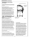
The grinder is equipped with a high-
low voltage relay which is factory
preset at 100-140 VAC. If the power
supply line does not deliver 100-140
VAC power under load, the relay will
open and trip out the starter. If this
occurs, your power supply line is
incorrect and must be correct before
proceeding further with the grinder.
A PROPER GROUND IS REQUIRED FOR SAFE
OPERATION OF THE EQUIPMENT. VERIFY THAT THE
RECEPTACLE GROUND IS A PROPER GROUND
BEFORE PLUGGING IN THE MACHINE.
IMPROPER GROUNDING IN YOUR BUILDING MAY
RESULT IN A DANGEROUS SHOCK TO THE OPERATOR
OR CAUSE THE GRINDER TO MALFUNCTION.
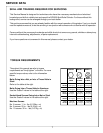
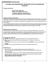
FOR 20 AMP RATED LARGE MACHINES
For 0 to 40 Feet (0 to 12 M) from panel to receptacle = Use 12 Ga. (4.0 mm) Wire.
For 40 to 60 Feet (12 to 18 M) from panel to receptacle = Use 10 Ga. (6.0 mm) Wire.
For 60 to 100 Feet (18 to 30 M) from panel to receptacle = Use 8 Ga. (10.0 mm) Wire.
For 100 to 160 Feet (30 to 48 M) from panel to receptacle = Use 6 Ga. (16.0 mm) Wire.
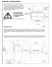
When installing the grinder, the following guidelines should be used
to establish the wire size between the power panel in your building
and the grinder receptacle. Note that the wiring in your building
must be per code between main power panels and sub panels.
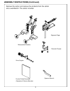
ASSEMBLY INSTRUCTIONS (Continued)