


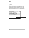

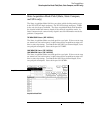
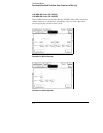
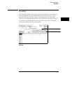
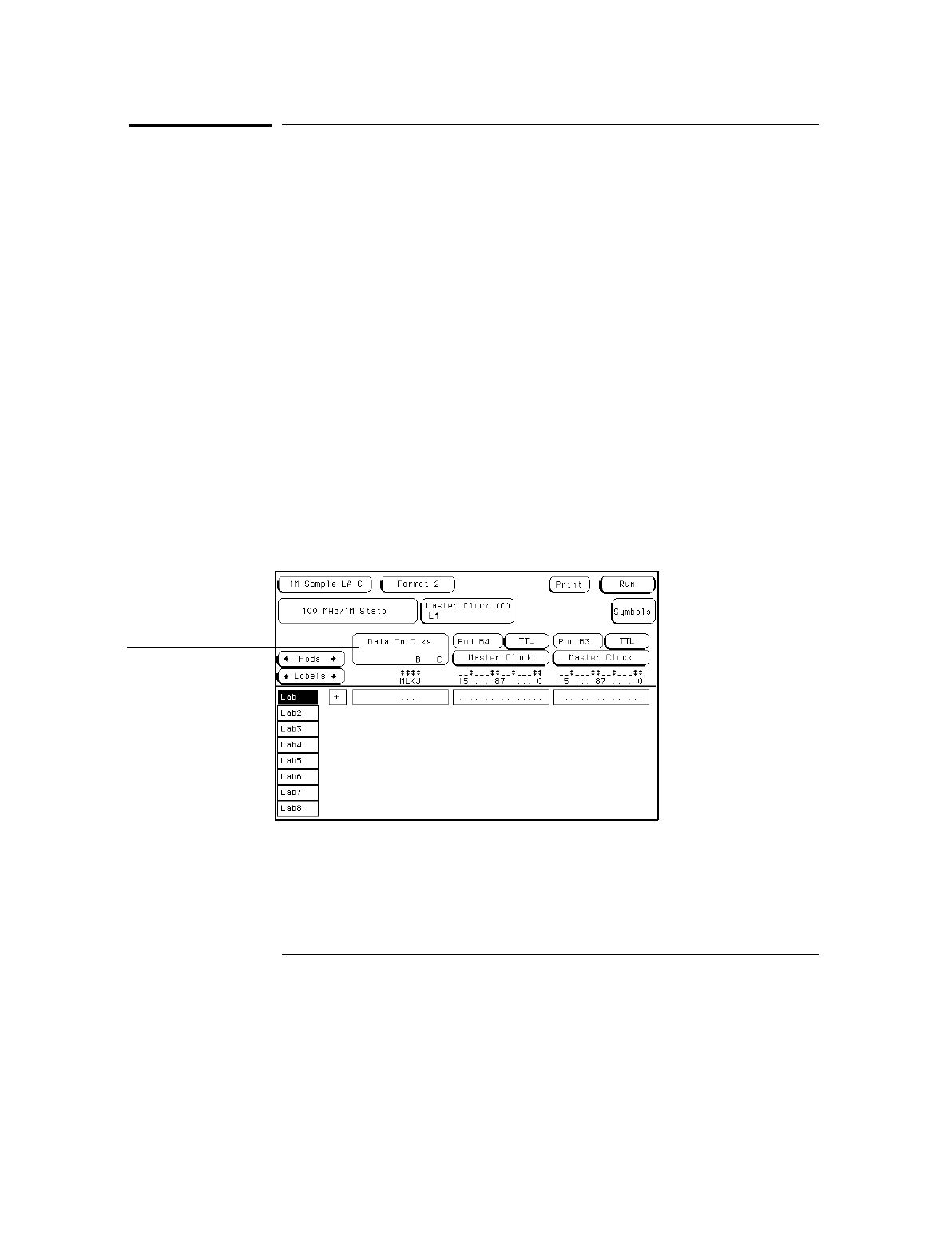
Data on Clocks Display
This display shows the clock input channels available for the present
configuration. There are four clock input channels (J, K, L, and M) for each
card of a module, one for each pod. This display shows only the clock input
channels for those pods that are assigned in the present configuration.
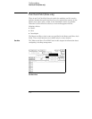
A single-card module has four clock input channels, each of which may be
used as a state clock (when the machine is configured for state mode) or as a
data channel (in either state or timing modes). In a multi-card module, only
the four clock input channels connected to the Clock Master card of the
module are available for use as state clocks, but all of the clock input
channels of the module (there are four for each card in the module) may be
used as data channels. A clock input channel, when used as a data channel,
is treated as an ordinary data channel, except it cannot be included in a
Range resource.
In the display panel, the clock input channels of the Clock Master card are
grouped on the right, underneath the slot letter of the Clock Master card,
with the clock input channels of the other cards displayed to the left of those
of the Clock master card. If any clock input channel is used as a data
channel, that bit must be assigned. Activity indicators above the clock
identifier show signal activity on that clock input channel.
Data on Clocks Display
Data on Clocks
display
The Format Menu
Data on Clocks Display
4–6