


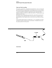
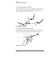

Probe Cable
The probe cable contains 17 signal lines, 17 chassis ground lines, and two
power lines for preprocessor use. The cables are woven together into a flat
ribbon that is 4.5 feet long. The probe cable connects the logic analyzer to
the pods, termination adapter, HP 10269C General-Purpose Probe Interface,
or preprocessor. Each cable is capable of carrying 0.33 amps for
preprocessor power.
CAUTION
DO NOT exceed this 0.33 amps per cable or the cable will be damaged.
WARNING
Preprocessor power is protected by a current limiting circuit. If the current
limiting circuit is activated, the fault condition must be removed. After the
fault condition is removed, the circuit will reset in one minute.
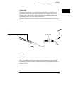
Minimum Signal Amplitude
Any signal line you intend to probe with the logic analyzer probes must
supply a minimum voltage swing of 500 mV to the probe tip. If you measure
signal lines with a voltage swing of less than 500 mV, you may not obtain a
reliable measurement.
Maximum Probe Input Voltage
The maximum input voltage of each logic analyzer probe is 40 volts peak.
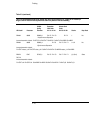
Pod Thresholds
Logic analyzer pods have two preset thresholds and a user-definable
threshold. The two preset thresholds are ECL (– 1.3 V) and TTL (+1.5 V).
The user-definable threshold can be set anywhere between – 6.0 volts and
+6.0 volts in 0.05-volt increments.
All pod thresholds are set independently.
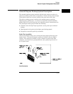
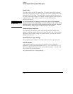
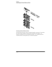
Probing
General-Purpose Probing System Description
2–20