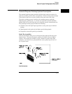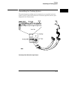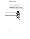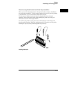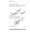
Connecting the External Reference Clock
The external reference clock synchronizes deep-memory logic analyzer
modules. Within a module, the individual cards all share a common clock and
are thus automatically synchronized. However, each module clock is
accurate only to 100 parts per million. So, two deep-memory logic analyzers
with identical settings may capture their trigger at the same time but show
discrepancies in the final sample. Sharing an external reference clock
prevents this.
To Connect the External Reference Clock
You can either supply your own external reference clock, or choose one of
the logic analyzer modules to supply the clock signal. Either method keeps
all connected modules synchronized.
1
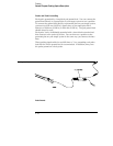
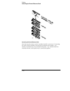
If you are supplying the clock signal, connect it to the "reference
clock in" of the master card of the top module.
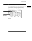
The Reference Clock field lets you specify whether to use the internal clock
provided on the card, or an external clock. If you select the external clock,
you must connect a clock signal to the card using the Reference Clock In/Out
ports on the back of the analyzer.
CAUTION
Do not exceed 1 V, peak-to-peak, at a maximum voltage offset of 20 V on the
Reference Clock In/Out ports.
2
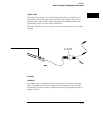
Cable the top module’s "reference clock out" to the "reference clock
in" of the master card of the next module.
3
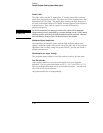
Continue connecting the modules in this manner.
Probing
Connecting the External Reference Clock
2–25


