


Voice Mode
MOTIF-RACK XS Owner’s Manual
90
Basic Structure
Reference
Voice
Multi Utility
The Controls &
Connectors
Setting Up
Listening to
the Sound
Connections
Using a Computer
Quick Guide
Appendix
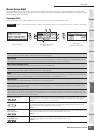
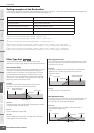
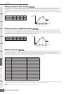
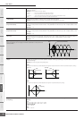
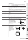
Setting example of Filter Scaling
Here we'll show you the setting example of Filter Scaling in Filter Scale (page 78) of the Voice Element Edit parameters. For the
settings shown in the example below, the basic Cutoff frequency value is 127, and the various Cutoff Offset values at the
selected Break Point settings change that basic value accordingly. The specific changes to the Cutoff frequency are shown in
the diagram below. The Cutoff frequency changes in a linear fashion between successive Break Points across the keyboard as
shown.
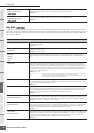
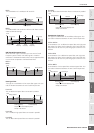
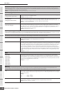
Setting example of Amplitude Scaling
Here we'll show you an example Amplitude Scaling setting in AMP Scale (page 81) of the Voice Element Edit parameters. For
the settings shown in the example below, the basic Amplitude (volume) value for the selected Element is 80, and the various
Level Offset values at the selected Break Point settings change that basic value accordingly. The Amplitude changes in a linear
fashion between successive Break Points across the keyboard as shown.
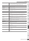
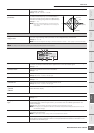
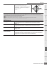
Output Select List
In the sections that follow, we'll explain the Output Select settings that let you determine the output assignments for the signals.
Output Select is specified in several different places: OSC (Oscillator) of the Drum Key Edit parameters (page 85) on the
MOTIF-RACK XS Editor, the mLAN In display of the Multi Common Edit parameter (page 92), the Play Mode display of the Multi
Part Editor parameters (page 95), and the Voice mLAN display of the Utility parameters.
*About “drum” setting, see below.
The “drum” setting can be selected in the Multi Part Edit display of the Parts assigned to the Drum Voice. When “drum” is selected and the Drum Voice is assigned
to the edited Part, the sound will be output via the destination set in the Drum Key Edit window as the “Output Select” parameter.
n The mLAN Inputs (m1 – m14) are available only when an optional mLAN16E2 has been installed.
1234
Break Point C#1D#2C3 C4
Cutoff Offset -4 +10 +17 +4
1234
Break Point C1 C2 C3 C4
Level Offset -4 +10 +17 +4
LCD Output jacks Stereo/Mono
L&R OUTPUT L and R Stereo
asL&R ASSIGNABLE OUTPUT L and R Stereo
m1&2 mLAN OUTPUT 1 and 2 Stereo (1: L, 2: R)
m3&4 mLAN OUTPUT 3 and 4 Stereo (3: L, 4: R)
m5&6 mLAN OUTPUT 5 and 6 Stereo (5: L, 6: R)
m7&8 mLAN OUTPUT 7 and 8 Stereo (7: L, 8: R)
m9&10 mLAN OUTPUT 9 and 10 Stereo (9: L, 10: R)
m11&12 mLAN OUTPUT 11 and 12 Stereo (11: L, 12: R)
m13&14 mLAN OUTPUT 13 and 14 Stereo (13: L, 14: R)
asL ASSIGNABLE OUTPUT L Mono
asR ASSIGNABLE OUTPUT R Mono
m1 mLAN OUTPUT 1 Mono
:: :
m14 mLAN OUTPUT 14 Mono
drum See below* See below*
123
137
144
131
Cutoff
frequency
Note
Break
Point 1
C#1
Break
Point 2
D#2
Break
Point 3
C3
Break
Point 4
A4
123
137
144
131
Amplitude
Note
Break
Point 1
C1
Break
Point 2
C2
Break
Point 3
C3
Break
Point 4
C4