


80 BCXC-SVX01B-EN
Diagnostics
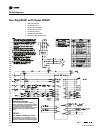
Table 48. Fresh air damper stays open
Probable cause Explanation
Normal operation The controller opens and closes the fresh air damper based on the controller’s occupancy mode and fan status. Normally,
the fresh air damper is open during occupied mode when the fan is running and closed during unoccupied mode.
Manual output test The controller includes a manual output test sequence that verifies analog and binary output operation and associated
wiring. However, based on the current step in the test sequence, the fresh air damper may be open. Refer to the “Manual
Output Test,” p. 73.
Unit configuration The controller must be properly configured based on the actual installed end devices and application. When the unit
configuration does not match the actual end device, the damper may not work correctly.
Unit wiring The wiring between the controller outputs and the fresh air damper must be present and correct for normal damper
operation. Refer to the unit wiring diagrams on the unit.
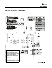
Table 49. Valves stay closed
Probable cause Explanation
Requested mode off You can communicate a desired operating mode (such as off, heat, and cool) to the controller. When off is communicated
to the controller, the unit controls the fan off. There is no heating or cooling (valves are closed).
Power-up control wait When power up control wait is enabled (non-zero time), the controller remains off until one of two conditions occurs:
The controller exits power up control wait once it receives communicated information.
The controller exits power up control wait once the power up control wait time expires.
Manual output test The controller includes a manual output test sequence you can use to verify output operation and associated output
wiring. However, based on the current step in the test sequence, the valve(s) may not be open. Refer to the “Manual
Output Test,” p. 73.
Fan mode off When a local fan mode switch (provided on the Trane zone sensor) determines the fan operation, the off position
controls the unit off and valves to close.
Sampling logic The controller includes entering water temperature sampling logic which is automatically invoked during 2-pipe and
4-pipe changeover when the entering water temperature is either too cool or too hot for the desired heating or cooling.
Refer to “Entering Water Temperature Sampling Function,” p. 55.
Diagnostic present A specific list of diagnostic affects valve operation. For more information, see Table 41, p. 77 and Table 42, p. 77.
Unit configuration The controller must be properly configured based on the actual installed end devices and application. When the unit
configuration does not match the actual end devices, the valves may not work correctly.
Example: A 2-pipe heat/cool changeover unit will not cool if the entering water temperature is too warm for cooling
or if the entering water sensor is not present. The unit will not heat if the entering water temperature is too cool for
heating.
Unit wiring The wiring between the controller outputs and the valve(s) must be present and correct for normal valve operation.
Random start observed After power up, the controller always observes a random start from 0 to 25 seconds. The controller remains off until
the random start time expires.
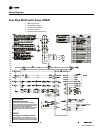
Table 50. DX or electric outputs do not energize
Probable cause Explanation
Unit wiring The wiring between the controller outputs and the end devices must be present and correct for normal operation.
Unit configuration The controller must be properly configured based on the actual installed end devices and application. When the unit
configuration does not match the actual end devices, the unit may not work correctly.
Diagnostic present A specific list of diagnostic affects valve operation. For more information, see Table 41, p. 77 and Table 42, p. 77.
Manual output test The controller includes a manual output test sequence you can use to verify output operation and associated output
wiring. However, based on the current step in the test sequence, the valve(s) may not be open. Refer to the “Manual
Output Test,” p. 73.
Freeze avoidance When the fan is off with no demand for capacity (0%) and the outdoor air temperature is below is below the freeze
avoidance setpoint, the controller disables compressors and electric heat outputs. This includes unoccupied mode when
there is no call for capacity or any other time the fan is off.
Normal operation The controller energizes the outputs only as needed to meet the unit capacity requirements.