


38 BCXC-SVX01B-EN
Installation Piping
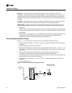
Water Coil Connections
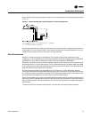
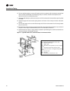
Water coils have sweat connections. Reference coil connection dimensions in “Dimensions and
Weights,” p. 15. Proper installation and piping is necessary to ensure satisfactory coil operation and
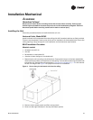
prevent operational damage. Water inlet and outlet connections extend through the coil section
side panel (see Figure 9). Follow standard piping practices when piping to the coil.
NOTICE
Potential coil-freeze condition!
Make provisions to drain the coil when not in use to prevent coil freeze-up. Failure to follow this
procedure could result in equipment/property damage.
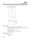
Piping Packages
Piping packages ship separate for field installation and have sweat type connections.
Interconnecting piping is field provided.
When brazing piping, follow these guidelines to prevent piping component damage.
1. Avoid exposing piping components to high heat when making sweat connections.
2. Protect the closest valve to the connection with a wet rag.
3. Ensure the circuit balancing valve option is in the unseated position.
Refrigerant Coil Piping
The DX cooling coil in a BCHC/BCVC unit is equipped with a single distributor (single-circuited).
Exception: size 72 and 90 six-row DX cooling coils are horizontally split and have two distributors
(double-circuited) which may be manifolded to a single refrigeration circuit in a condensing unit.
Some condensing units have two, independent refrigeration circuits. Do not manifold two,
independent refrigeration circuits into a single-circuited DX (evaporator) coil.
Note: Refer to “Warnings, Cautions and Notices” for information on handling refrigerants.
Units that are UL listed shall not have refrigerant temperatures and pressures exceeding that listed
on the unit nameplate.
Follow accepted refrigeration piping practices and safety precautions for typical refrigerant coil
piping and components. Specific recommendations are provided with the compressor unit,
including instructions for pressure-testing, evacuation, and system charging. Leak test the entire
refrigerant system after all piping is complete. Charge the unit according to approximate weight
requirements, operating pressures, and superheat/subcooling measurements. Adjust the thermal
expansion valve setting, if necessary, for proper superheat.
Liquid Line
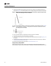
Line Sizing. Properly sizing the liquid line is critical to a successful application. If provided, use
the liquid line size recommended by the manufacturer of the compressor unit. The selected tube
Figure 9. Horizontal unit coil connect location