


BCXC-SVX01B-EN 7
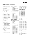
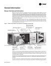
Following is a complete description of
the blower coil model number. Each
digit in the model number has a
corresponding code that identifies
specific unit options.
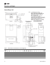
Digits 1, 2, 3, 4 — Unit Model
BCHC= horizontal blower coil
BCVC= vertical blower coil
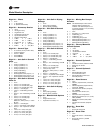
Digits 5, 6, 7 — Unit Size
Digit 8 — Unit Voltage
Digit 9 —Insulation Type
1 = 1” matte-faced
2 = 1” foil-faced
Digits 10, 11 — Design Sequence
A0
Digit 12 — Motor, Drive, and
Control Box Location
A = same side as coil connections,
horizontal or counterswirl only
B = opposite side from coil
connections, horizontal or
counterswirl only
C = same side as coil connections,
pre-swirl only
D = opposite side from coil
connections, pre-swirl only
R = right-hand access
L = left-hand access
Digit 13 — Drain Pan Type, Coil
& Drain Connection Side
0 = none
1 = polymer drain pan & right-hand
connections
2 = polymer drain pan & left-hand
connections
3 = stainless steel drain pan & right-
hand connections
4 = stainless steel drain pan & left-
hand connections
012 024 054
018 036 072 090
A = 115/60/1 H = 575/60/3
B = 208/60/1 J = 220/50/1
C = 230/60/1 K = 240/50/1
D = 277/60/1 L = 380/50/3
E = 208/60/3 M = 415/50/3
F = 230/60/3 N = 190/50/3
G = 460/60/3 P = two-speed,
115/60/1
0 = no motor, ctrls, elec ht.
Digit 14 — Unit Coil #1*
Note: All coils are hydronic unless stated
otherwise.
0 = none
A = 1-row preheat
L = 2-row hydronic high-capacity
preheat
F = 4-row hydronic
G = 6-row hydronic
J = 4-row hydronic, autochangeover
K = 6-row hydronic, autochangeover
M = 4-row hydronic high-capacity
N = 6-row hydronic high-capacity
R = 4-row hydronic high-capacity,
autochangeover
T = 6-row hydronic high-capacity,
autochangeover
1 = 3-row DX, 3/16” distributor
(0.032)
2 = 4-row DX, 3/16” distributor
(0.032)
3 = 6-row DX, 3/16” distributor
(0.032)
4 = 3-row DX, 3/16” distributor
(0.049)
5 = 4-row DX, 3/16” distributor
(0.049)
6 = 6-row DX, 3/16” distributor
(0.049)
Digit 15 — Unit Coil #2*
Note: All coils are hydronic unless stated
otherwise.
0 = none
A = 1-row reheat
L = 2-row hydronic high-capacity
reheat
F = 4-row hydronic
G = 6-row hydronic
H = 2-row hydronic, autochangeover
J = 4-row hydronic, autochangeover
K = 6-row hydronic, autochangeover
M = 4-row hydronic high-capacity
N = 6-row hydronic high-capacity
P = 2-row hydronic high-capacity,
autochangeover
R = 4-row hydronic high-capacity,
autochangeover
T = 6-row hydronic high-capacity,
autochangeover
1 = 3-row DX, 3/16” distributor
(0.032)
2 = 4-row DX, 3/16” distributor
(0.032)
3 = 6-row DX, 3/16” distributor
(0.032)
4 = 3-row DX, 3/16” distributor
(0.049)
5 = 4-row DX, 3/16” distributor
(0.049)
6 = 6-row DX, 3/16” distributor
(0.049)
Digit 16 — Motor Horsepower
Digit 17 — Motor Drives
0 = none
A = 390–552 rpm / 60 Hz
B = 478–678 rpm / 60 Hz
C = 540–765 rpm / 60 Hz
D = 619–878 rpm / 60 Hz
E = 727–1029 rpm / 60 Hz
F = 879–1245 rpm / 60 Hz
G = 1000–1417 rpm / 60 Hz
H = 1200–1700 rpm / 60 Hz
J = 1313–1859 rpm / 60 Hz
K = 1615–2288 rpm / 60 Hz
L = 678–877 rpm / 60 Hz
M = 765–990 rpm / 60 Hz
N = 878–1136 rpm / 60 Hz
P = 1029–1332 rpm / 60 Hz
R = 1245–1611 rpm / 60 Hz
T = 1174–1519 rpm / 50 Hz
Digit 18 — Electric Heat Stages
0 = none
1=1-stage
2 = 2-stage
Digits 19, 20, 21 — Electric Heat
Digit 22 — Electric Heat Controls
0 = none
A = 24 volt magnetic contactors
B = 24 volt mercury contactors
Digit 23 — Electric Heat Options
0 = none
A = electric heat with heater fuse
B = electric heat interlocking non-
fused disconnect
C=A & B
0 = none 4 = 1 hp
1 = 1/3 hp 5 = 1-1/2 hp
2 = 1/2 hp 6 = 2 hp
3 = 3/4 hp 7 = 3 hp
000 = none 100 = 10.0 kW
010 = 1.0 kW 110
=
11.0 kW
015 = 1.5 kW 120
=
12.0 kW
020 = 2.0 kW 130 = 13.0 kW
025 = 2.5 kW 140 = 14.0 kW
030 = 3.0 kW 150 = 15.0 kW
035 = 3.5 kW 160 = 16.0 kW
040 = 4.0 kW 170 = 17.0 kW
045 = 4.5 kW 180 = 18.0 kW
050 = 5.0 kW 190 = 19.0 kW
055 = 5.5 kW 200 = 20.0 kW
060 = 6.0 kW 210 = 21.0 kW
065 = 6.5 kW 220 = 22.0 kW
070 = 7.0 kW 240 = 24.0 kW
075 = 7.5 kW 260 = 26.0 kW
080 = 8.0 kW 280 = 28.0 kW
090 = 9.0 kW 300 = 30.0 kW
Model Number Description