


40 BCXC-SVX01B-EN
Installation Piping
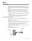
Routing. To prevent residual or condensed refrigerant from “free-flowing” toward the
compressor, install the suction line so it slopes slightly—1 inch per 10 feet of run [1 cm per 3 m]—
toward the evaporator. Avoid putting refrigerant lines underground. Refrigerant condensation,
installation debris inside the line, service access, and abrasion/corrosion can quickly impair system
reliability.
Insulation. After operating the system and testing all fittings and joints to verify the system is
leak-free, insulate the suction lines to prevent heat gain and unwanted condensation.
Components. Installing the suction line requires field installation of these components: an
access port and possibly a suction filter. Position them as close to the compressor as possible.
• Access port
The access port is used to determine suction pressure and adjust the TEV. It should be located
near the external equalizer line connection. This port is usually a Schraeder valve with a core.
• Suction filter
If required by the compressor unit, a replaceable-core suction filter is installed as close to the
compressor unit as possible. Adding manual, ball-type shutoff valves upstream and
downstream of the filter simplifies replacement of the filter core.
Field-Installing Evaporator Piping
See Figure 10 and refer to the instructions below to field-install evaporator piping.
1. Pitch the liquid line slightly—1 in./10 ft [1 cm/3 m]—so that the refrigerant drains toward the
evaporator.
2. Provide one expansion valve per distributor.
3. Slightly pitch the outlet line from the suction header toward the suction riser — that is, 1 in./10
ft [1 cm/3 m] in the direction of flow. Use the tube diameter that matches the suction-header
connection.
4. For the vertical riser, use the tube diameter recommended by the condensing unit
manufacturer. Assure the top of the riser is higher than the evaporator coil.
5. Arrange the suction line so the refrigerant vapor leaving the coil flows downward, below the
suction-header outlet, before turning upward.
6. Pitch the suction line slightly—1 in./10 ft [1 cm/3 m]—so the refrigerant drains toward the
evaporator.
7. Insulate the suction line.
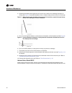
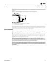
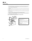
Figure 10. Field-installed evaporation piping example
thermal
expansion
valve (TXV)
liquid
line
filter driersolenoid
valve
sight
glass
distributor
suction line
Evaporator Coil with
Standard Circuiting