


BCXC-SVX01B-EN 79
Diagnostics
Table 45. Valves stay open
Probable cause Explanation
Normal operation The controller opens and closes the valves to meet the unit capacity requirements.
Valve override The controller can communicate a valve override request to affect the valve operation.
Manual output test The controller includes a manual output test sequence that verifies analog and binary output operation and the
associated wiring. However, based on the current step in the test sequence, the valves may be open. Refer to the
“Manual Output Test,” p. 73.
Diagnostic present A specific list of diagnostics affects valve operation. For more information, see Table 41, p. 77 and Table 42, p. 77.
Sampling logic The controller includes entering water temperature sampling logic that automatically invokes during 2-pipe or 4-pipe
changeover to determine if the entering water temperature is correct for the unit operating mode. Refer to “Entering
Water Temperature Sampling Function,” p. 55.
Unit configuration The controller must be properly configured based on the actual installed end devices and application. When the unit
configuration does not match the actual end device, the valves may not work correctly.
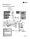
Unit wiring The wiring between the controller outputs and the valve(s) must be present and correct for normal valve operation.
Refer to the unit wiring diagrams on the unit.
Table 46. Electric heat not operating
Probable cause Explanation
Normal operation The controller cycles electric heat on and off to meet the unit capacity requirements.
Requested mode: off It is possible to communicate the operating mode (such as off, heat, cool) to the controller. When off is communicated
to the controller, the units shuts off the electric heat.
Communicated disable Numerous communicated requests may disable electric heat, including an auxiliary heat enable input and the heat/
cool mode input. Depending on the state of the communicated request, the unit may disable electric heat.
Manual output test The controller includes a manual output test sequence that verifies analog and binary output operation and associated
output wiring. However, based on the current step in the test sequence, the electric heat may not be on. Refer to the
“Manual Output Test,” p. 73.
Diagnostic present A specific list of diagnostics affects electric heat operation. For more information, see Table 41, p. 77 and Table 42,
p. 77.
Unit configuration The controller must be properly configured based on the actual installed end devices and application. When the unit
configuration does not match the actual end device, the electric heat may not work properly.
No power to the
controller
If the controller does not have power, the unit fan does not operate. For the Tracer™ ZN010, 510 controller to operate
normally, it must have an input voltage of 24 VAC. When the green LED is off continuously, the controller does not have
sufficient power or has failed.
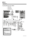
Unit wiring The wiring between the controller outputs and the electric heat contacts must be present and correct for normal electric
heat operation. Refer to the unit wiring diagrams on the unit.
Table 47. Fresh air damper stays closed
Probable cause Explanation
Warm-up and cool-down The controller includes both a warmup and cooldown sequence to keep the fresh air damper closed during the transition
from unoccupied to occupied. This is an attempt to bring the space under control as quickly as possible.
Requested mode: off It is possible to communicate the operating mode (such as off, heat, cool) to the controller. When off is communicated
to the controller, the unit closes the fresh air damper.
Manual output test The controller includes a manual output test sequence that verifies analog and binary output operation and associated
output wiring. However, based on the current step in the test sequence, the fresh air damper may not be open. Refer
to the “Manual Output Test,” p. 73.
Diagnostic present A specific list of diagnostics effects fresh air damper operation. For more information, see Table 41, p. 77 and Table 42,
p. 77.
Unit configuration The controller must be properly configured based on the actual installed end devices and application. When the unit
configuration does not match the actual end device, the damper may not work correctly.
No power to the
controller
If the controller does not have power, the unit fan does not operate. For the Tracer™ ZN010, 510 controller to operate
normally, it must have an input voltage of 24 VAC. When the green LED is off continuously, the controller does not have
sufficient power or has failed.
Unit wiring The wiring between the controller outputs and the fresh air damper must be present and correct for normal damper
operation. Refer to the unit wiring diagrams on the unit.