


26 BCXC-SVX01B-EN
Installation Controls
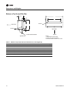
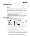
b. Pull the control wires through the cutout. Attach the module to the wall using the screws
provided.
5. Strip the insulation on the interconnection wires back 0.25 inch and connect to TB1. Screw down
the terminal blocks.
6. Replace the zone sensor cover and adjustment knob.
If installing a Tracer™ ZN510 or ZN520 zone sensor, see “Tracer Summit Communication Wiring,”
p. 27 for more information.
Communication Wiring
Units with Tracer ZN510 or ZN520 only
Note: Communication link wiring is a shielded, twisted pair of wire and must comply with
applicable electrical codes.
Follow these general guidelines when installing communication wiring on units with either a
Tracer™ ZN510 or ZN520 controller:
• Maintain a maximum 5000 ft. aggregate run
• Install all communication wiring in accordance with the NEC and all local codes.
• Solder the conductors and insulate (tape) the joint sufficiently when splicing communication
wire. Do not use wire nuts to make the splice.
• Do not pass communication wiring between buildings because the unit will assume different
ground potentials.
• Do not run power in the same conduit or wire bundle with communication link wiring.
Service Communication Wiring
Establish service communication using Rover™ service software connected to the Tracer™ ZN
controller using a twisted wire pair to one of the following connection points:
• Remote zone sensor module
• Connections on the board
This allows the technician to view and edit the Tracer™ controller configuration and troubleshoot
the unit.
Note: Unit control options and field wiring practices may limit the controller’s communication
ability.
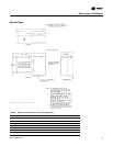
Route interconnecting wiring from the Tracer™ controller to provide service communication at the
wall-mounted zone sensor module. Install wiring by referencing the unit wiring diagram and
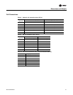
Table 12, p. 29 for appropriate wire sizes. After wiring is complete, connect the communication
cable (provided with the Rover™ service tool) to the telephone style RJ11 connection on the zone
sensor module. Attach the other end of the cable to a computer running Trane Rover software to
communicate.
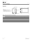
Zone Sensors Without Interconnecting Wiring
Establish service communication to the Tracer™ ZN controller by wiring directly to the board inside
the control box. Refer to the unit-wiring diagram for appropriate communication terminals on the
board.
Once wiring is complete, Use Trane Rover™ software to communicate to the Tracer™ ZN controller.
Tracer Communications
Tracer™ ZN controllers have Comm5 communication ports. Typically, a communication link is
applied between unit controllers and a building automation system. Communication also is
possible via Rover™, Trane’s service tool.