


BCXC-SVX01B-EN 37
Installation Mechanical
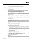
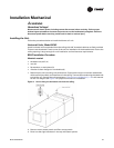
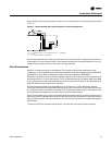
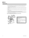
Plug or trap the auxiliary connection to prevent air from being drawn in and causing carryover (see
Figure 8).
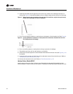
All drain lines downstream of the trap must flow continuously downhill. If segments of the line are
routed uphill, this can cause the drain line to become pressurized. A pressurized drain line may
cause the trap to back up into the drain pan, causing overflow.
Duct Connections
Install all air ducts according to the National Fire Protection Association standards for the
“Installation of Air Conditioning and Ventilation Systems other than Residence Type (NFPA 90A)
and Residence Type Warm Air Heating and Air Conditioning Systems (NFPA 90B).
Make duct connections to the unit with a flexible material such as heavy canvas to help minimize
noise and vibration. If a fire hazard exists, Trane recommends using Flexweave 1000, type FW30
or equivalent canvas. Use three inches for the return duct and three inches for the discharge duct.
Keep the material loose to absorb fan vibration.
Run the ductwork straight from the opening for a minimum of 1-1/2 fan diameters. Extend
remaining ductwork as far as possible without changing size or direction. Do not make abrupt turns
or transitions near the unit due to increased noise and excessive static losses. Avoid sharp turns
and use elbows with splitters or turning vanes to minimize static losses.
Poorly constructed turning vanes may cause airflow generated noise. Align the fan outlet properly
with the ductwork to decrease duct noise levels and increase fan performance. Check total external
static pressures against fan characteristics to be sure the required airflow is available throughout
the ductwork.
To achieve maximum acoustical performance, minimize the duct static pressure setpoint.
Figure 8. Recommended drain trap installation for draw-through units
‘
H = 1” of length for each 1” of negative pressure + 1”additional
J = 1/2 of H
L = H + J + pipe diameter + insulation