


BCXC-SVX01B-EN 29
Installation Electrical
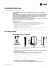
3. If the unit has a electric heat: power and ground connections are inside the electric heat control
box, connected to a non-fused disconnect switch or terminal block.
Electrical Grounding Restrictions
ƽ WARNING
Hazardous Voltage!
Disconnect all electric power, including remote disconnects before servicing. Follow proper
lockout/tagout procedures to ensure the power can not be inadvertently energized. Failure to
disconnect power before servicing could result in death or serious injury.
All sensor and input circuits are normally at or near ground (common) potential. When wiring
sensors and other input devices to the Tracer™ ZN controller, avoid creating ground loops with
grounded conductors external to the unit control circuit. Ground loops can affect the measurement
accuracy of the controller.
Note: Unit transformer IT1 provides power to the blower coil unit only and is not intended for field
connections. Field connections to the transformer IT1 may cause immediate or premature
unit component failure.
All input/output circuits (except isolated relay contacts and optically-isolated inputs) assume a
grounded source, either a ground wire at the supply transformer to control panel chassis, or an
installer supplied ground.
Note: Do not connect any sensor or input circuit to an external ground connection.
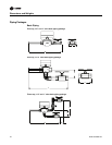
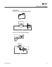
The installer must provide interconnection wiring to connect wall mounted devices such as a zone
sensor module. Refer to the unit wiring schematic for specific wiring details and point-to-point
wiring connections. Dashed lines indicate field wiring on the unit wiring schematics. All
interconnection wiring must conform to NEC Class 2 wiring requirements and any state and local
requirements. Refer to Table 12 for the wire size range and maximum wiring distance for each
device.
Note: Do not bundle or run interconnection wiring in parallel with or in the same conduit with any
high voltage wires (110V or greater). Exposure of interconnection wiring to high voltage
wiring, inductive loads, or RF transmitters may cause radio frequency interference (RFI). In
addition, improper separation may cause electrical noise problems. Therefore, use shielded
wire (Beldon 83559/83562 or equivalent) in applications that require a high degree of noise
immunity. Connect the shield to the chassis ground and tape at the other end.
Minimum Circuit Ampacity (MCA) and Maximum Fuse Size (MFS) Calculations
for Units with Electric Heat
Use these formulas to calculate the MCA and MFS.
Heater amps = (heater kW x 1000)/heater voltage
Note: Use 120V heater voltage for 115V units. Use 240V heater voltage for 230V units. Use 480V
heater voltage for 460V units. Use 600V heater voltage for 575V units.
MCA = 1.25 x (heater amps + all motor FLAs)
MFS or HACR type circuit breaker = (2.25 x largest motor FLA) + second motor FLA + heater amps
(if applicable)
HACR (Heating, Air-Conditioning and Refrigeration) type circuit breakers are required in the branch
circuit wiring for all units with electric heat.
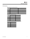
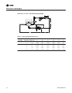
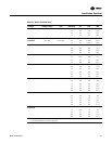
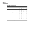
Table 12. Zone sensor maximum wiring distances, ft (m)
Wire size range Max. wiring distance
16–22 AWG 200 (60.96)