


28 BCXC-SVX01B-EN
Installation Electrical
Unit Wiring Diagrams
Specific unit wiring diagrams are provided on the inside of the control panel door. Typical unit
wiring diagrams are in “Wiring Diagrams,” p. 81. Use these diagrams for connections or trouble
analysis.
ƽ WARNING
Grounding Required!
Follow proper local and state electrical codes for requirements on grounding. Failure to follow
code could result in death or serious injury.
Supply Power Wiring
Wiring must conform to NEC and all applicable code requirements.
It is the installer’s responsibility to provide adequately-sized power wires and proper unit
grounding.
Bring supply wiring through provided equipment knockouts located at the power connection point
on the unit. Equipment submittals should be referred to for the exact electrical access connection
point. Connect the power wires to the power connection point provided.
Connection to the installer-provided ground path must be made to the green wire or green
grounding screw provided on each unit.
Locate unit wiring diagrams on the inside of the control box cover. Refer to the unit-specific wiring
diagrams for wiring, connection point, and fuse installation information. Refer to the unit
nameplate for unit-specific electrical information, such as voltage, minimum circuit ampacity
(MCA), and maximum fuse size (MFS).
ƽ WARNING
Hazardous Voltage!
Disconnect all electric power, including remote disconnects before servicing. Follow proper
lockout/tagout procedures to ensure the power can not be inadvertently energized. Failure to
disconnect power before servicing could result in death or serious injury.
NOTICE
Use copper conductors only!
Unit terminals are not designed to accept other conductor types. Failure to use copper
conductors could cause equipment damage.
NOTICE
Correct phase critical!
Correct phase sequence is critical. If phase sequence of the incoming line voltage is not correct,
it could cause motor damage.
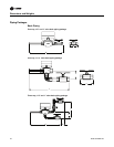
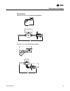
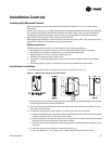
Electrical Connections
Units have one of three different connection points, depending on the unit type and options.
1. If the unit has no controls: power and ground are tucked inside of the handy box.
2. If the unit has a control interface or Tracer™ ZN controller: power and ground are inside the
control box. If the unit has a control interface or a Tracer controller, the power wires and ground
wire are inside the control box connected to a non fused disconnect switch.