


72 BCXC-SVX01B-EN
Diagnostics
Troubleshooting
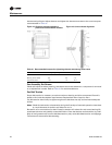
LED Activity
Red Service LED
The red LED normally indicates if the unit controller is operating properly or not. Refer to Table 36.
Green Status LED
The green LED normally indicates whether the controller is powered on (24 VAC supplied). Refer
to Table 37.
Yellow Comm LED
The yellow comm LED blinks at the rate the controller receives communication. The yellow LED
does not blink when the controller is transmitting communication data. Refer to Table 38 .
Note: If the service push button is held down for more than 15 seconds, the Tracer™ ZN controller
will uninstall itself from the ICS communication network and shut down all unit operation.
This mode is indicated by the red Service LED flashing once every second. See the Red
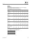
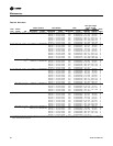
Table 36. Red service LED activity‘
LED activity Description
Off continuously after power is applied to the controller. Normal operation
On continuously, even when power is first applied to the
controller.
Someone is pressing the Service button or the controller
has failed.
LED flashes about once every second. Uninstall (normal controller mode). Use Rover™ service
tool to restore normal unit operation.
Black Service push button. Use the Service button to install the Tracer™ ZN520
controller in a communication network.
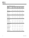
Table 37. Green status LED activity
Green LED activity Description
On continuously Power on (normal operation).
Blinks (one blink)
The controller is in manual output test mode.
No diagnostics present.
Blinks (two blinks)
The controller is in manual output test mode.
One or more diagnostics are present.
LED blinks (1/4 second on, 1/4 second, off for 10 seconds) Wink mode.
(a)
(a)The Wink feature allows you to identify a controller. By sending a request from Rover™ service tool, you can request the
controller to wink (blink on and off as a notification that the controller received the signal). The green LED blinks (1/4
second on, 1/4 second off for 10 seconds) during Wink mode.
LED off
Power is off.
Controller failure.
Test button is pressed.
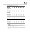
Table 38. Yellow comm LED activity
LED activity Description
Off continuously The controller is not detecting any communication.
(Normal for standalone applications.)
LED blinks or flickers The controller detects communication.
(Normal for communicating applications, including data sharing.)
LED on continuously Abnormal condition or extremely high traffic on the link.
High traffic on the link.