


BCXC-SVX01B-EN 27
Installation Controls
Peer-to-peer communication across controllers is possible even when a building automation
system is not present.You do not need to observe polarity for Comm5 communication links.
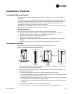
The controller provides six 0.25-inch quick-connect terminals for the Comm5 communication link
connections, as follows:
• Two terminals for communication to the board
• Two terminals for communication from the board to the next unit (daisy chain)
• Two terminals for a connection from the zone sensor back to the controller
Each controller has its own unique address or I.D. number on a Neuron chip. Setting dip switches
are not required on the Tracer™ controller.
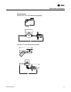
Tracer Summit Communication Wiring
For Tracer™ ZN-controlled units that will interface with the Trane Tracer Summit® building
management system, terminate the communication wiring in the control box at the designated
terminals on the board. Reference the unit wiring diagram or submittals.
Ground shields at each Tracer™ ZN controller, taping the opposite end of each shield to prevent
any connection between the shield and anther ground. Refer to Trane publication CNT-SVX04A-EN,
Tracer ZN.520 Unit Controller - Installation, Operation and Programming Guide, for the
communication wiring diagram.
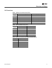
Communication wire must conform to the following specification:
• Shielded twisted pair 18 AWG
• Capacitance 23 (21-25) picofarads (pF) per foot
• Listing/Rating – 300V 150C NEC 725-2 (b) Class 2 Type CL2P
• Trane Part No. 400-20-28 or equivalent, available through Trane BAS Buying Group Accessories
catalog.