


BCXC-SVX01B-EN 41
Installation Piping
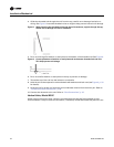
Steam Piping
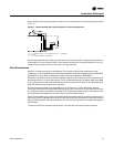
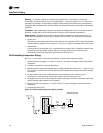
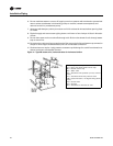
Proper installation, piping and trapping is necessary to insure satisfactory heating coil operation
and prevent operational damage under service conditions. These installation recommendations
and piping diagram (see Figure 11, p. 42) must be followed to assure satisfactory, trouble-free
operation.
General
1. Support all piping independently of coils.
2. Provide swing joints or flexible fittings in all piping connections adjacent to heating coils to
absorb expansion and contraction strains.
3. Install coils so air passes through fins in proper direction (stenciled on top of coil channel).
Steam Coils
NOTICE
Coil Condensate!
Condensate must flow freely from the coil at all times to prevent coil damage from water
hammer, unequal thermal stresses, freeze-up and/or corrosion. In all steam coil installations, the
condensate return connections must be at the low point of the coil. Failure to follow these
instructions could result in equipment damage.
1. Install 1/2-inch 15-degree swing check vacuum breaker in unused condensate return tapping as
close as possible to coil. Vent vacuum breaker line to atmosphere or connect into return main
at discharge side of steam trap. Vacuum relief is particularly important when coil is controlled
by modulating steam supply or two-position (on-off) automatic steam supply valve.
2. Proper steam trap selection and installation is necessary for satisfactory coil performance and
service life.
a. Select trap based on maximum possible condensate rate and recommended load factors.
b. Locate steam trap discharge at least 12 inches below condensate return tapping. This
provides sufficient hydrostatic head pressure to overcome trap losses and assure complete
condensate removal.
c. Float and thermostatic traps are preferred because of gravity drain and continuous
discharge operation.
d. Use float and thermostatic traps with atmospheric pressure gravity condensate return with
automatic controls or where possibility of low pressure supply steam exists.
e. Bucket traps should only be used when supply steam is unmodulated and 25 psig or higher.
f. When installed with series airflow, size traps for each coil using capacity of first coil in airflow
direction.
g. Always trap each coil separately to prevent condensate holdup in one or more coils.
h. Always install strainers as close as possible to inlet side of trap.
3. Use V-port modulating valves to obtain gradual modulating action or slow opening 2-position
valves to prevent steam hammer.
Note: Contact the factory for recommendations regarding steam coil valve selections
compatible with Tracer™ ZN controllers.
4. Use normally-open non-modulating control valves if coils are exposed to freezing air.
Note: Contact the factory for recommendations regarding steam coil valve selections
compatible with Tracer™ ZN controllers.
5. Control each coil bank separately when installing coils for series airflow with automatic steam
control valves.