


BCXC-SVX01B-EN 39
Installation Piping
diameter must be as small as possible, while still providing at least 5°F [2.7°C] of subcooling at the
expansion valve throughout the operating envelope.
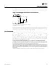
Routing. Install the liquid line with a slight slope in the direction of flow so that it can be routed
with the suction line. Minimize tube bends and reducers because these items tend to increase
pressure drop and reduce subcooling at the expansion valve.
Insulation. The liquid line is generally warmer than the surrounding air, so it does not require
insulation.
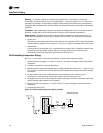
Components. Liquid-line refrigerant components necessary for a successful job include an
expansion valve, moisture indicating sight glass, filter drier, manual ball shutoff valves, access
port, and possibly a solenoid valve. Position these components as close to the evaporator as
possible.
• Thermal expansion valve (TEV)
Select the TEV based on the actual evaporator capacity, considering the full range of loadings.
Verify that the valve will successfully operate at the lightest load condition, considering if hot
gas bypass is to be used. For improved modulation, choose a TEV with balanced port
construction and an external equalizer connection. The valve must be designed to operate
against a back pressure of 20 psi higher than actual evaporator pressure. Install the TEV directly
on the coil liquid connection (distributor provided).
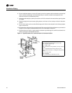
The remote expansion-valve bulb should be firmly attached to a straight, well-drained,
horizontal section of the suction line. The external equalizer line should be inserted
downstream of the remote bulb.
• Moisture-indicating sight glass
Install a moisture-indicating sight glass in the liquid line between the expansion valve and filter
drier. The sight glass should be sized to match the size of the liquid line.
• Filter drier
Install a properly sized liquid line filter-drier upstream from the expansion valve and as close
to the evaporator coil as possible. Select the filter-drier for a maximum pressure drop of 2 psi
at the design condition.
Manual, ball-type shutoff valves on either side of the filter drier allows replacement of the core
without evacuating the entire refrigerant charge.
• Access port
The access port allows the unit to be charged with liquid refrigerant and is used to determine
subcooling. This port is usually a Schraeder valve with a core.
• Solenoid valve
If required by the compressor unit, install the solenoid valve between the filter drier and sight
glass.
NOTICE
Valve Damage!
Disassemble the thermal expansion valve before completing the brazing connections. If
necessary, wrap the valve in a cool wet cloth while brazing. Failure to protect the valve from
high temperatures could damage internal components.
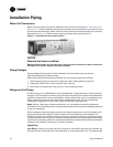
Suction Line
Line sizing. Properly sizing the suction line is critical for ensuring that the oil returns to the
compressor throughout the system operating envelope. If provided, use the suction line size(s)
recommended by the manufacturer of the compressor unit. The selected tube diameter(s) must
maintain adequate refrigerant velocities at all operating conditions.