


78 BCXC-SVX01B-EN
Diagnostics
Common Diagnostics
Table 43. Fan outputs do not energize
Probably cause Explanation
Random start observed After power-up, the controller always observes a random start that varies between 0 and 30 seconds. The controller
remains off until the random start time expires.
Power-up control wait When power-up control wait is enabled (non-zero time), the controller remains off until one of two conditions occurs:
1. The controller exits power-up control wait once it receives communicated information.
2. The controller exits power-up control wait once the power-up control wait time expires.
Cycling fan operation When the fan mode switch is in the auto position, the unit fan cycles off when there is no call for heating or cooling.
The heating/cooling sources cycle on or off periodically with the unit fan to match the capacity according to pulse width
modulation (PWM) logic.
Unoccupied operation The fan cycles with capacity when the unit is in unoccupied mode. This occurs even if the unit is in continuous fan
operation. While unoccupied, the fan cycles on or off with heating/cooling to provide varying amounts of heating or
cooling to the space. to match the capacity diagnostics according to pulse-width-modulation (PWM) logic.
Fan mode off When using the local fan mode switch to determine the fan operation, the off position controls the unit fan to off.
Requested mode: off It is possible to communicate the operating mode (such as off, heat, and cool) to the controller. When “off” is
communicated to the controller, the unit controls the fan to off. The unit is not capable of heating or cooling when the
controller is in this mode.
Diagnostic present A specific list of diagnostics affects fan operation. For more information, see Table 41, p. 77 and Table 42, p. 77.
No power to the
controller
If the controller does not have power, the unit fan does not operate. For the Tracer™ ZN controller to operate normally,
it must have an input voltage of 24 VAC. When the green LED is off continuously, the controller does not have sufficient
power or has failed.
Unit configuration The controller must be properly configured based on the actual installed end devices and application. When the unit
configuration does not match the actual end devices, the valves may not work correctly.
Manual output test The controller includes a manual output test sequence to verify binary output operation and the associated wiring.
However, based on the current step in the test sequence, the unit fan may not be powered on. Refer to “Manual Output
Test,” p. 73.
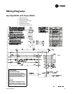
Unit wiring The wiring between the controller outputs and the fan relays and contacts must be present and correct for normal fan
operation. Refer to the specific unit wiring diagrams on the unit.
Table 44. Valves stay closed
Probable cause Explanation
Normal operation The controller opens and closes the valves to meet the unit capacity requirements.
Requested mode: off It is possible to communicate the operating mode (such as off, heat, and cool) to the controller. When off is
communicated to the controller, the unit controls the fan to off. The unit is not capable of heating or cooling when the
controller is in this mode.
Valve override The controller can communicate a valve override request.This request affects the valve operation.
Manual output test The controller includes a manual output test sequence to verify analog and binary output operation and the associated
wiring. However, based on the current step in the test sequence, the valves may not be open. Refer to the “Manual
Output Test,” p. 73.
Diagnostic present A specific list of diagnostics affects valve operation. For more information, see Table 41, p. 77 and Table 42, p. 77.
Sampling logic The controller includes entering water temperature sampling logic that automatically invokes during 2-pipe or 4-pipe
changeover. It determines when the entering water temperature is either too cool or too hot for the desired heating
or cooling mode. Refer to “Entering Water Temperature Sampling Function,” p. 55.
Unit configuration The controller must be properly configured based on the actual installed end devices and application. When the unit
configuration does not match the actual end device, the valves may not work correctly.
No power to the
controller
If the controller does not have power, the unit fan does not operate. For the Tracer™ ZN010, 510 controller to operate
normally, it must have an input voltage of 24 VAC. When the green LED is off continuously, the controller does not have
sufficient power or has failed.
Unit wiring The wiring between the controller outputs and the valve(s) must be present and correct for normal valve operation.
Refer to the unit wiring diagrams on the unit.