


8 BCXC-SVX01B-EN
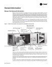
Model Number Description
Digit 24 — Filters
0 = none
A = 1” throwaway
B = 2” pleated throwaway
Digit 25 — Accessory Section
Digit 26 — Control Type
0 = no controls (4 x 4 junction box)
1 = control interface
2 = Tracer™ ZN010
3 = Tracer ZN510
4 = Tracer ZN520
Digit 27 — Unit Coil #1 Control
Valve
0 = none
A = 2-way, 2-position, n.c.
B = 2-way, 2-position, n.o.
C = 3-way, 2-position, n.c.
D = 3-way, 2-position, n.o.
E = 2-way modulating
F = 3-way modulating
G = field-supplied valve, 2-pos., n.c.
H = field-supplied valve, 2-pos., n.o.
J = field-supplied modulating valve
Digit 28 — Unit Coil #1 Control
Valve Cv
0 = none
A = 3.3 Cv, 1/2” valve & pipe
B = 3.3 Cv, 1/2” valve & 3/4” pipe
C = 3.8 Cv, 1/2” valve & 3/4” pipe
D = 6.6 Cv, 1” valve & pipe
E = 7.4 Cv, 1” modulating valve &
pipe
F = 8.3 Cv, 1-1/4” modulating valve &
pipe
G = 3.5 Cv, 1/2” valve & pipe
H = 4.4 Cv, 1/2” valve & pipe
J = 7.0 Cv, 3-way valve
OR 6.0 Cv, 2-way valve, 1” valve
& pipe
K = 8.0 Cv, 1” valve & pipe
L = 7.4 Cv, 1” 2-position valve & pipe
M = 8.3 Cv, 1-1/4” 2-position valve &
pipe
Q = 1.3 Cv, 1/2” valve, 3/4” pipe
R = 1.8 Cv, 1/2” valve, 3/4” pipe
T = 2.3 Cv, 1/2” valve, 3/4” pipe
U = 2.7 Cv, 1/2” valve, 3/4” pipe
0 = none
A = mixing box only
B = angle filter box
C = angle filter/mixing box
D = top access filter box
E = bottom access filter
F = A & D L = C & H
G = A & E M = D & H
H = steam coil N = E & H
J = A & H P = A, D, & H
K = B & H R = A, E, & H
Digit 29 — Unit Coil #1 Piping
Package
0 = none
1 = basic piping package
2 = deluxe piping package
Digit 30 — Unit Coil #2 Control
Valve
0 = none
A = 2-way, 2-position, n.c.
B = 2-way, 2-position, n.o.
C = 3-way, 2-position, n.c.
D = 3-way, 2-position, n.o.
E = 2-way modulating
F = 3-way modulating
G = field-supplied valve, 2-pos., n.c.
H = field-supplied valve, 2-pos., n.o.
J = field-supplied modulating valve
Digit 31 — Unit Coil #2 Control
Valve Cv
0 = none
A = 3.3 Cv, 1/2” valve & pipe
B = 3.3 Cv, 1/2” valve & 3/4” pipe
C = 3.8 Cv, 1/2” valve & 3/4” pipe
D = 6.6 Cv, 1” valve & pipe
E = 7.4 Cv, 1” modulating valve &
pipe
F = 8.3 Cv, 1-1/4” modulating valve &
pipe
G = 3.5 Cv, 1/2” valve & pipe
H = 4.4 Cv, 1/2” valve & pipe
J = 7.0 Cv, 3-way valve
OR 6.0 Cv, 2-way valve, 1” valve
& pipe
K = 8.0 Cv, 1” valve & pipe
L = 7.4 Cv, 1” 2-position valve & pipe
M = 8.3 Cv, 1-1/4” 2-position valve &
pipe
Q = 1.3 Cv, 1/2” valve, 3/4” pipe
R = 1.8 Cv, 1/2” valve, 3/4” pipe
T = 2.3 Cv, 1/2” valve, 3/4” pipe
U = 2.7 Cv, 1/2” valve, 3/4” pipe
Digit 32 — Unit Coil #2 Piping
Package
0 = none
1 = basic piping package
2 = deluxe piping package
Digit 33 — Remote Heat Options
0 = none
1 = staged electric heat
2 = 2-position hot water, n.c.
Digit 34 — Mixing Box Damper
Actuator
Note: The back damper is the control
damper when actuators are
ordered. The back damper is n.c.
(normally closed) or n.o. (normally
open) as selected.
0 = none
1 = 2-position, n.o., ship loose
2 = modulating, n.c.
3 = modulating, n.o.
4 = modulating, ship loose
5 = field-supplied 2-position, n.o.
6 = field-supplied 2-position, n.c.
7 = field-supplied modulating
Digit 35 — Factory Mounted
Control Options
Digit 36 — Control Options 2
0 = none
A = outside air sensor, field-mounted
B = discharge air sensor
C=A & B
Digit 37 — Control Options 3
0 = none
A = dehumidification with
communicated value
B = dehumidification with local
humidity sensor
Digit 38 — Zone Sensors
0 = none
1 = off/auto, setpoint knob, on/cancel,
COMM
2 = off/auto/high/low, setpoint knob,
on/cancel, COMM
3 = wall mtd. zone sensor (set point,
occ, COMM)
4 = wall mtd. zone sensor (occ,
COMM)
5 = wall mtd. zone temp sensor
A = digital zone sensor (O, A, H, L; SP;
OCC; COMM)
B = digital zone sensor (CPS; OCC;
COMM)
C = wireless zone sensor (setpoint
only)
Digit 39 — Extra Belt
0 = none
1 = ship loose extra belt
Digit 40 — Extra Filter
0 = none
1 = ship loose extra 1” throwaway
filter
2 = ship loose extra 2” pleated
throwaway
0 = none
A = fan status
C = condensate overflow
D = low limit
F = A & C K = C & D
G = A & D N = A, C, & D