


36 BCXC-SVX01B-EN
Installation Mechanical
• interconnecting linkage, LH or RH attachment
Materials needed:
• grooved and extendible drive rods, 1/2-inch O.D. grooved
• screws
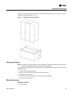
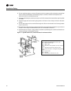
The mixing box option ships separately for field installation. It has two low-leak, opposed blade
dampers and all necessary interconnecting linkage components for left or right hand attachment
onto 1/2-inch O.D. grooved, extendible drive rods. Also, mounting legs are provided for floor
mounting on a vertical unit. Knockouts are provided to suspend the mixing box from the ceiling
horizontally.
Mixing Box Installation Procedure
1. Support the mixing box independent of the unit in the horizontal position.
2. Install the mixing box as a sleeve around the duct collar of the filter frame. To attach the mixing
box to the filter frame, insert screws through the matching the holes on all sides of the mixing
box and filter frame.
3. Install the linkage, following the procedure below.
Linkage Installation Procedure
1. Attach the linkage on either the right or left side of the mixing box following the procedure
below.
2. Open the damper blades fully. Locate drive rods on the LH or RH side for linkage attachment.
Loosen drive rod set screw, without removing.
3. Remove knockouts on side access panel adjacent to the drive rods.
4. Pierce a hole through the insulation at the knockouts to allow the drive rod to extend freely
through side of mixing box. Cut away insulation sufficiently to allow drive rod to turn smoothly.
5. Extend drive rod end at desired position beyond side of unit. Tighten drive rod set screws.
6. Attach linkage and tighten all set screws. Note that neither hand levers are provided. However,
mixing box actuators are a factory-provided option that ship inside the mixing box when
ordered.
7. Position linkage so both sets of dampers operate freely and so that when one damper is fully
open, the other is fully closed.
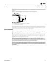
Condensate Drain Connections
Note: It is the installer’s responsibility to provide adequate condensate piping to prevent potential
water damage to the equipment and/or building.
Size the main drain lines and trap them the same size as the drain connection, which is 3/4”
schedule 40 PVC, 1.050” O.D. on blower coils.
If drain pan removal is required, make the main and auxiliary drain connections with compression
fittings. Follow the procedure below to remove the drain pan.
1. Remove the opposite side coil access panel.
2. Remove the drain pan clips.
3. Disconnect drain lines.
4. Remove the sheet metal screw.
5. Pull out drain pan through the opposite side.
Note: Prime drain traps to prevent the drain pan overflow.