


60 BCXC-SVX01B-EN
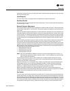
Start-Up
Zone Sensor
The Tracer™ ZN controller accepts the following zone sensor module inputs:
• Space temperature measurement (10kW thermistor)
• Local setpoint (either internal or external on the zone sensor module)
• Fan mode switch
• Timed override, using “on” and “cancel” buttons (Tracer ZN510 and ZN520 only)
• Communication jack (Tracer ZN510 and ZN520 only)
Space Temperature Measurement
Zone sensors use a 10kW thermistor to measure the space temperature. Wall-mounted zone
sensors include a space temperature thermistor. Unit-mounted zone sensors have a return air
sensor mounted in the unit’s return airstream. If both a hardwired and communicated space
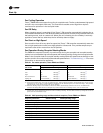
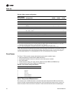
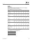
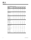
Table 29. Binary output configuration
Binary output
pin connection Configuration ZN010 ZN510 ZN520
J1-1 Fan high •••
J1-2 N/A •••
J1-3 Fan low •
J1-4 (Key) •
Fan low ••
J1-5 Main valve – open, or 2 pos. valve
(a)
(a) Two-pipe hydronic heat/cool changeover units use terminals J1-5 and J1-6 to control the primary valve for both heating and
cooling. Units configured and applied as 2-pipe hydronic heat/cool changeover with electric heat, use terminals J1-5 and
J1-6 to control the primary valve (for both cooling and heating), and terminals J1-9 and J1-10 for the electric heat stage.
For those 2-pipe changeover units, electric heat will not energize while the hydronic supply is hot (5 or more degrees
above the space temperature). In a 4-pipe application, pin J1-5 is for cooling and pin J1-6 for heating.
•••
J1-6 Aux. valve/elec. ht. ••
Aux. valve – close
(a)
•
J1-7 2-pos. damper ••
J1-9 Heat valve – open, or 2 pos. valve, or first stage elec. ht.
(a)
•
J1-10 Heat valve – close or sec. stage elec. ht.
(a)
•
J1-11 Fresh air damper – open •
J1-12 Fresh air damper – close •
TB4-1 Generic / baseboard heat output •
TB4-2 24 VAC •
Notes:
1. If no valves are ordered with the unit, the factory default for Tracer™ ZN010 and ZN510 controllers are: main valve
configured as normally closed and aux. valve configured as normally open.
2. If the fresh air damper option is not ordered on the unit, 2-pos. damper is configured as none.
3. Pin J1-2 can be configured for an exhaust fan with the use of Rover™ software. Factory default is none.
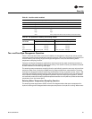
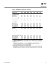
Table 30. Zone sensor wiring connections
TB1 Description
1Space temperature
2Common
3Setpoint
4Fan mode
5 Communications
6 Communications