


Greensmaster eFlex 1800/2100 Page 4 -- 41 Electrical System
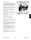
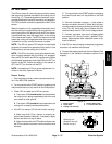
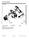
5. Use a multimeter to measure voltage across the
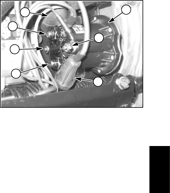
main contactor posts as follows:
A. Position rubber boots away from main contactor
posts to allow access to posts with multimeter
probes (Fig. 53).
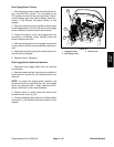
B. Connect multimeter common (--) test probe to
ground connector in work light connector (step 4
above).
C. Make sure that traction lever is in the NEUTRAL
position. Temporarily connect battery pack (see Lith-
ium Battery Pack Connection in the General Infor-
mation section of this chapter).
D. TurnkeyswitchtotheSTARTpositiontowakeup
the machine and then turn key switch to the RUN
position. The main contactor should click as it is en-
ergized.
E. Using the second multimeter test probe, verify
that all four (4) posts on main contactor have system
voltage (42V to 64V @ 100% state of charge) pres-
ent (Fig. 53). If one (1) or more posts DO NOT have
system voltage present, the contactor is faulty. If
none of the posts have voltage present, make sure
that common (--) test probe is still connected to work
light connector and if so, look for electrical issues at
other machine components as the contactor is not
being energized correctly.
F. TurnkeyswitchtotheOFFposition.Themain
contactor should click as it is de--energized.
G. Disconnect the battery pack (see Lithium Battery
Pack Connection in the General Information section
of this chapter).
6. If testing determines that main contactor is faulty,
make sure that battery pack is disconnected and then
replace main contactor.
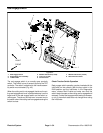
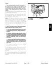
7. When main contactor testing is complete, install
power center cover to machine (Fig. 51).
8. Connect the battery pack (see Lithium Battery Pack
Connection in the General Information section of this
chapter).
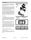
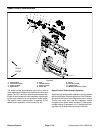
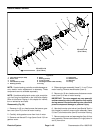
1. Main contactor
2. Rubber boot
3. Main contact post
4. Coil post
Figure 53
3
2
1
2
3
4
4
Electrical
System