Greensmaster eFlex 1800/2100Traction and Reel Drive System Page 3 -- 40
Transmission
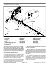
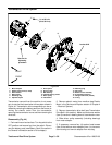
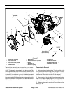
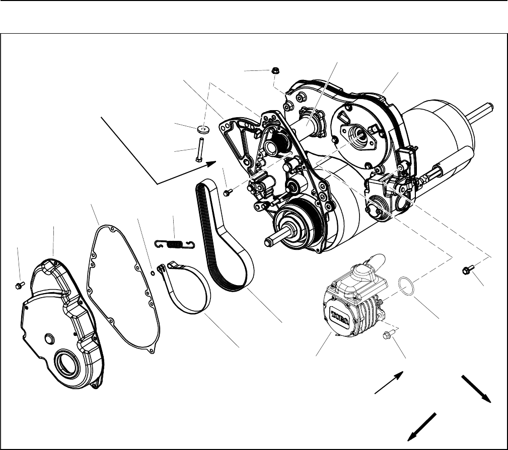
Figure 47
1. Transmission assembly
2. Flange head screw
3. O--ring
4. Flange head screw (2 used)
5. Electric motor assembly
6. Drum drive belt
7. Brak e band
8. Washer head screw (11 used)
9. Drum drive cover
10. Gasket
11. Retaining ring
12. Extension spring
13. Cap screw
14. Hardened washer
15. RH drum drive housing
16. Flange head screw
17. Extension housing
FRONT
RIGHT
See text for
tightening
procedure
2
13
1
3
6
8
9
10
11
5
12
4
7
8
14
15
16
17
21 to 25 ft--lb
(29to33N--m)
Transmission removal from the machine is not neces-
sary in order to service internal transmission compo-
nents. Transmission components can be accessed by
removing the battery pack from the frame, removing the
transmission cover and then removing the transmission
drive belt. If transmission removal is desired, proceed
with the following steps. Once the transmission has
beenremoved from the machine, service procedures for
internal transmission components are described earlier
in this section.
Transmission Removal
1. Parkmachineon level surface. Turnkeyswitchto the
OFF position and remove key from the switch. Discon-
nect the battery pack (see Battery Pack Connection in
the General Information section of this chapter).
2. Disconnect reel clutch cable from transmission (see
Reel Clutch Cable Replacement in the Service and Re-
pairs section of Chapter 6 -- Chassis and Controls).
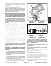
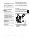
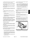
3. Slide the telescoping coupler off the cutting unit h ex
shaft (Fig. 48).


