


Greensmaster eFlex 1800/2100 Page 4 -- 23 Electrical System
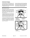
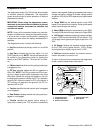
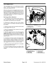
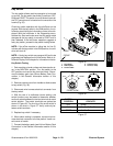
Traction Switch
The traction switch is a normally open proximity switch.
The switch is attached to the handle assembly switch
mount bracket (Fig. 27).
When the t raction engagement lever is not engaged, the
head of the cap screw in the traction lever is positioned
away from the target end of the traction switch so the
switch is in its normal open state. The head of the cap
screw in the traction engagement lever is moved toward
the switch target when the traction lever is engaged
causing the switch to close.
Traction Switch Adjustment
1. Park machine on level surface and place traction le-
ver in the NEUTRAL position. Turn key switch to the
OFF position and remove key from the switch.
2. Disconnect the battery pack (see Lithium Battery
Pack Connection in the General Information section of
this chapter).
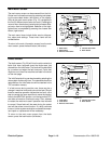
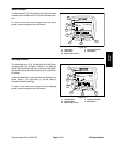
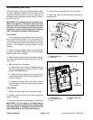
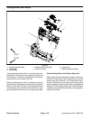
3. Remove console cover from handle to allow access
to traction switch (Fig. 28).
4. Move the traction engagement lever forward to the
engaged position.
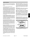
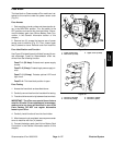
5. With the traction engagement lever in the engaged
position, there should be from 0.030” to 0.120” (0.8 to
3.0 mm) clearance between the head of the cap screw
in the traction lever and the traction switch (Fig. 27).
NOTE: With traction lever pushed fully forward against
its rotation stop, the head of the cap screw should not
deflect the traction switch more than 0.030” (0.8 mm).
The traction lever will rotate back slightly once latched.
At that point, the required clearance (0.030” to 0.120”)
should be maintained.
6. If clearance is incorrect, loosen traction switch
mounting fasteners, adjust clearance and tighten fas-
teners. Recheck clearance between screw head and
switch after tightening fasteners. The screw head must
not contact the switch.
7. When traction switch adjustment is completed,
install console cover t o handle.
8. Connect the battery pack (see Lithium Battery Pack
Connection in the General Information section of this
chapter).
1. Engagement lever
2. Traction switch
3. Cap screw head
Figure 27
1
3
2
1. Traction switch
2. Engagement lever assy
3. Lower handle
4. Screw (2 used)
5. Lock nut (2 use d)
6. Console cover
7. Screw (4 used)
8. Switch mount bracket
Figure 28
5
3
1
2
6
4
7
8
FRONT
RIGHT
Electrical
System