


Greensmaster eFlex 1800/2100Page 6 -- 16Cutting Unit
Bedbar Adjuster Service
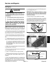
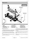
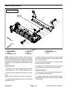
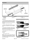
Figure 23
1. Bedbar assembly
2. Compression spring
3. Lock nut
4. Bedbar adjuster shaft
5. Flange bushing
6. Cap screw
7. Detent
8. Wave washer
9. Retaining ring
10. Bedbar adjuster screw
11. Washer
FRONT
RIGHT
Antiseize
Lubricant
2
3
6
8
9
10
11
1
5
7
4
5
eFlex 2100 Shown
NOTE: The detent (item 7) used on eFlex 2100 is to-
ward the center of the cutting unit as shownin Figure 23.
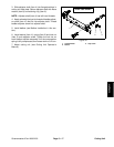
On eFlex 1800 cutting units, the detent is mounted on
the outside of the cutting unit crossmember (Fig. 24).
Cutting unit service procedures are the same on both
models.
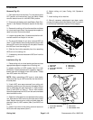
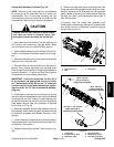
Removal (Fig. 23)
1. Remove lock nut (item 3), compression spring (item
2) and washer (item 11) from bedbar adjuster screw.
2. Remove bedbar (see Bedbar Removal in this sec-
tion).
NOTE: Adjuster shaft (item 4) has left--hand threads.
3. Unscrewbedbar adjuster shaft (item4) from thebed-
bar adjuster screw.
4. Remove retaining ring (item 9) and wave washer
(item 8) from adjuster shaft and remove a djuster shaft
from cutting unit frame.
5. Inspect flange bushings (item 5) in cutting unit side
plate and remove if necessary.
6. If detent (item 7) is damaged, remove it from cutting
unit side plate by r emoving the cap screw (item 6).
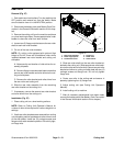
Installation (Fig. 23)
1. If detent (item 7) was removed, secure detent to cut-
ting unit side plate with cap screw.
2. If flange bushings (item 5) were removed, align key
on bushing to slot in frame and install bushingsin cutting
unit side plates.