


M300EU INTRODUCTION
Addendum to M300EU Manual - P/N 04288
1. INTRODUCTION
This addendum is based on the M300E/EM Operators Manual (P/N 04288). It is intended as a supplement to
the M300E/EM manual (P/N 04288) and provides an overview of the instrument operation and specific details
regarding those areas where the M300EU is different in design or operating method from the M300E.
In most ways the M300EU is identical to the M300E/EM in design and operation, therefore most of the basic set
up information, operating instructions as well as calibration, maintenance, troubleshooting and repair methods
are the same and can be found in the M300E/EM manual (P/N 04288).
1.1. REFERENCE NUMBERING CONVENTION
Unless otherwise specified, chapter, section, figure and table reference numbers referred to within this text are
relative to this document.
• EXAMPLE: “Table 2-1” refers to the figure, within this document, labeled as 2-1.
• Additionally, in the electronic version(s) of this manual references internal to this document will be active
links to that section, figure or table.
References to chapters, sections, figures and tables in the original document will be labeled as such and will not
be an active link.
• EXAMPLE: “Figure 6.1 of the M300E/EM Operators Manual (P/N 04288)”.
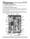
1.2. M300EU OVERVIEW
NOTE
The information contained in this addendum is relevant to M300EU analyzers running: SOFTWARE
REVISION K.6. Some or all of the information may not be applicable to earlier or later revisions of
software.
The software revision your analyzer is running is displayed in the upper left-hand corner of the display
any time the instrument is in SETUP mode.
The model 300EU is a close derivative of the M300E/EM CO Analyzer, however its higher sensitivity require
some changes its design and operation.
The primary differences between the M300EU and the M300E/EM analyzers are:
• INTERFERENT REJECTION: Periodically the sample gas stream is routed through an internal CO
scrubber allowing the instrument to make a measurement of the sample gas completely free of CO; the
measurement made during this auto-reference period (A-REF) is subtracted from the sample
concentration measurement. This corrects for instrument drift, ambient temperature changes and
changing CO
2
levels in the sample gas.
• OPERATING METHOD: An additional operating mode is added allowing the user to manipulate several
parameters associated with the A-REF measurement cycle.
• SAMPLE GAS CONDITIONING: A Nafion
®
drier is used to dry the sample and alleviate any effects from
humidity changes in the sample gas.
• IR OPTICS: The objective and field mirrors on the optical bench are gold plated. This maximizes their
reflectivity and increasing the amount of IR light reaching the detector and improving the optical bench’s
signal-to-noise performance.
• PNEUMATIC OPERATION: The flow rate is higher. It has a 1.8 LPM nominal flow rate. The flow
sensor is rated to 6 LPM.
• MECHANICAL DESIGN: The optical bench is placed in a temperature-controlled, convection-heated
oven. This dramatically reduces instrument noise and temperature related drift.
05904 Rev A 1