


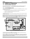

M300EU THEORY OF OPERATION
(Addendum to M300EU Manual - P/N 04145)
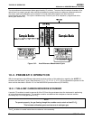
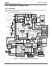
10.2.2. THE A-REF VALVE ASSEMBLY
The auto-reference valve assembly is located next to the optical bench, at the rear of the analyzer between the
Nafion
®
dryer and the outer wall of the instrument (see Figure 3-1). The following table describes the state of
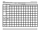
each valve during the analyzer’s various operational modes (see Figure 10-1).
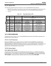
Table 10-1: Auto-Reference Valve Operating States
Mode Valve State VALVE PORT CONNECTIONS
SAMPLE
(Normal State)
Gas stream from Nafion
®
Dryer &
SAMPLE inlet
3 Æ 2
A-REF DWELL
Gas stream from CO scrubber
1 Æ 2
A-REF MEASUREMENT
Gas stream from CO scrubber
1 Æ 2
SAMPLE DWELL
Gas stream from Nafion
®
Dryer &
SAMPLE inlet
3 Æ 2
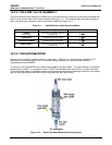
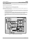
10.2.3. THE NAFION
®
DRYER.
Normal room air contains a certain amount of water vapor. While H
2
O is a very low-level interferent for IR
absorption (in the same range as CO) it can cause enough interference to affect the high-resolution
measurements of the M300EU.
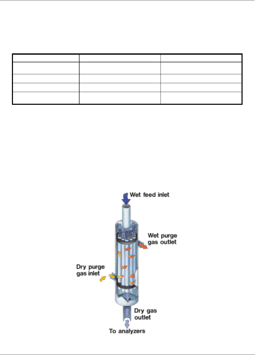
To account for this the M300EU has a special dryer added to the gas stream. The dryer consists of a bundle of
parallel tubes of Nafion
®
, a co-polymer similar to Teflon
®
that absorbs water very well but not other chemicals.
The multiple tube design of this dryer creates a large reactive surface without causing a restriction in the higher
gas flow rate required by the M300EU that a long single tube style dryer would.
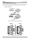
Figure 10-3: Semi-Permeable Membrane Drying Process
05514 Rev A1 51