


M300EU OPERATING INSTRUCTIONS M300EU
Addendum to M300E/EM Manual P/N 04288
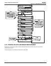
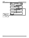
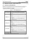
6.7.3. SELECTING A TEST CHANNEL FUNCTION FOR OUTPUT A4
This section replaces Section 6.13.5.5 of the M300E/EM Operators Manual (P/N 04288)
The Test Functions available to be reported on analog output A4 are:
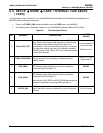
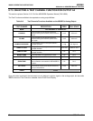
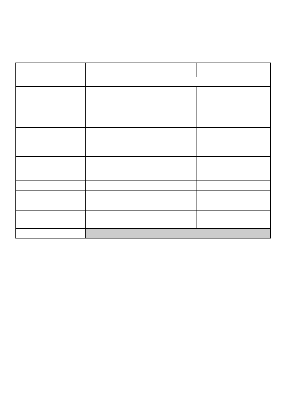
Table 6-6: Test Channels Functions Available on the M300EU’s Analog Output
TEST CHANNEL DESCRIPTION ZERO FULL SCALE
NONE TEST CHANNEL IS TURNED OFF
CO MEAS
The raw output of the optical bench’s IR
detector during the measure phase of the m/r
cycle
0 mV 5000 mV*
CO REF
The raw output of the optical bench’s IR
detector during the reference phase of the
m/r cycle
0 mV 5000 mV*
SAMPLE PRESSURE
The pressure of gas in the optical bench’s
sample chamber
0 "Hg 40 "Hg-In-A
SAMPLE FLOW
The gas flow rate through the optical bench’s
sample chamber
0 cm
3
/min 6000 cm
3
/min
SAMPLE TEMP
The temperature of gas in the optical bench’s
sample chamber
0 C° 70 C°
BENCH TEMP
The temperature of optical bench’s itself
0 C° 70 C°
WHEEL TEMP
The temperature of GFC wheel
0 C° 70 C°
OVEN TEMP
The temperature of the circulating air inside
the convection oven section of the M300EU’s
interior.
0 C° 70 C°
PHT DRIVE
The drive voltage being supplied to the
thermoelectric coolers of the IR photo-detector by
the sync/demod Board.
0 mV 5000 mV
TEMP4
SPARE
Once a function is selected, the instrument not only begins to output a signal on the analog output, but also adds
TEST to the list of Test Functions viewable via the Front Panel Display.
38 05831 Rev. 01