


M300EU OPERATING INSTRUCTIONS M300EU
Addendum to M300E/EM Manual P/N 04288
6.2.2. TEST FUNCTIONS
The information found in Section 6.2.1 of the M300E/EM Operators Manual (P/N 04288) is applicable to the
M300EU with the following exception(s):
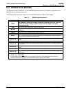
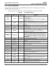
• The following table supersedes Table 6-2 of the M300E/EM Operators Manual (P/N 04288).
Table 6-2: Test Functions Defined
Parameter Display Title
Units
Meaning
RANGE
- -
RANGE1
RANGE2
RANGE
PPB, PPM
UGM, MGM
The full-scale limit at which the output range of the analyzer’s Analog
Outputs is currently set.
• THIS IS NOT the Physical Range of the instrument. See Section 6.3.2
for more information.
If DUAL or AUTO Range modes have been selected, two RANGE functions
will appear, one for each range.
Stability STABIL
PPB, PPM
UGM, MGM
Standard deviation of CO concentration readings. Data points are recorded
every ten seconds using the last 25 data points. This function can be reset
to show O
2
or CO
2
stability in instruments with those sensor options
installed.
CO Measure MEAS MV
The demodulated, peak IR detector output during the measure portion of the
CFG Wheel cycle.
CO Reference REF MV
The demodulated, peak IR detector output during the reference portion of
the CFG wheel cycle.
Measurement /
Reference Ratio
MR Ratio -
The result of CO MEAS divided by CO REF based on readings taken during
the normal sample measurement portion of the A-REF cycle.
This ratio is the primary value used to compute CO concentration. The
value displayed is not linearized.
Auto-Reference
Ratio
AZERO RATIO -
The result of CO MEAS divided by CO REF based on readings
taken during the zero-reference portion of the A-REF cycle.
This ratio is the used to compute a reference correction factor
for computing the CO concentration. The value displayed is
not linearized.
Sample Pressure PRES In-Hg-A
The absolute pressure of the Sample gas as measured by a pressure
sensor located inside the sample chamber.
Sample Flow SAMPLE FL
cm
3
/min
Sample mass flow rate as measured by the flow rate sensor in the sample
gas stream,
Sample
Temperature
SAMP TEMP
°C
The temperature of the gas inside the sample chamber.
Bench
Temperature
BENCH TEMP
°C
Optical bench temperature.
Wheel
Temperature
WHEEL TEMP
°C
GFC wheel temperature.
Box Temperature BOX TEMP
°C
The temperature inside the analyzer chassis.
Oven
Temperature
OVEN TEMP
2
°C
The current temperature of the circulating air inside the M300EU’s
convection oven area.
Photo-detector
Temp. Control
Voltage
PHT DRIVE mV
The drive voltage being supplied to the thermoelectric coolers of the IR
photo-detector by the sync/demod Board.
Slope SLOPE -
The sensitivity of the instrument as calculated during the last calibration
activity. The SLOPE parameter is used to set the span calibration point of
the analyzer.
Offset OFFSET -
The overall offset of the instrument as calculated during the last calibration
activity. The OFFSET parameter is used to set the zero point of the
analyzer response.
Test Channel
Output
TEST mV
The raw voltage being output on the analyzer’s A4 analog output. Only
appears when the test channel is assigned a function.
Current Time TIME -
The current time. This is used to create a time stamp on iDAS readings, and
by the AUTOCAL feature to trigger calibration events.
22 05831 Rev. 01