


GETTING STARTED M300EU
Addendum to M300E/EM Manual P/N 04288
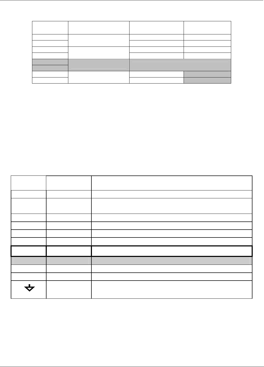
Table 3-2: Analog Output Pin Outs
Pin Analog Output
Standard Voltage
Output
Current
Loop Option
1 V Out I Out +
2
A1
Ground I Out -
3 V Out I Out +
4
A2
Ground I Out -
5
6
A3
NOT USED
7 V Out Not Available
8
A4
Ground Not Available
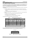
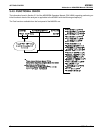
3.3.3. CONNECTING THE STATUS OUTPUTS
The information found in Section 3.1.2.3 is correct with the following exception:
Table 3-3: Status Output Pin Assignments
Output #
Status
Definition
Condition
1 SYSTEM OK On if no faults are present.
2
CONC VALID
On if CO concentration measurement is valid.
If the CO concentration measurement is invalid, this bit is OFF.
3 HIGH RANGE
On if unit is in high range of DUAL or AUTO Range Modes.
4 ZERO CAL On whenever the instruments ZERO point is being calibrated.
5 SPAN CAL On whenever the instruments SPAN point is being calibrated.
6 DIAG MODE On whenever the instrument is in DIAGNOSTIC mode.
7
A-REF On whenever the instrument in is A-REF mode.
8 SPARE
D
EMITTER BUSS The emitters of the transistors on pins 1-8 are bussed together.
+
DC POWER + 5 VDC
Digital Ground The ground level from the analyzer’s internal DC Power Supplies.
8 05831 Rev. 01