


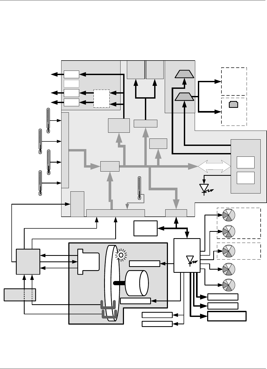
M300EU THEORY OF OPERATION
(Addendum to M300EU Manual - P/N 04145)
10.3. ELECTRONIC OPERATION
10.3.1. OVERVIEW
The information found in Section 10.4.1 of the M300E/EM Operators Manual (P/N 04288) is applicable to the
M300EU with the following exception(s):
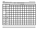
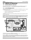
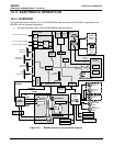
• This figure replaces Figure 10-9of the M300E/EM Operators Manual.
Serial I/O
Ports
INTERNAL PUMP
Analog Outputs
Aout 1
Aout 4
Analog
Outputs
(D/A)
External
Digital I/O
Power Up
Circuit
P
C
1
0
4
B
u
s
PC 104
CPU Card
Disk on
Chip
Flash
Chip
COM
1
COM
2
Aout 3
Aout 2
TEST CHANNEL OUTPUT
Status
Outputs
1 - 8
Control
Outputs
1 – 6
RS-232
or RS-485
RS-232
CPU
Status
LED
I
2
C Bus
Keyboard
& Display
Wheel Heater
Sensor Inputs
Chassis
Temperature
A/D
Converter
SPAN Valve
(Optional)
Shutoff Valve
(Optional)
ZERO Valve
(Optional)
Sample Gas
Temperature
Optical Bench
Temperature
CO Concentration RANGE2
CO Concentration RANGE1
Measure/
Reference
Valve
Optional
Ethernet
Card
Optional
Multidrop
Card
MOTHERBOARD
Auto-
Reference
Valve
Oven
Temperature
GFC Wheel
Temperature
Thermistor Interface
Internal
Digital I/O
SYNC
DEMOD
IR Photo-
detector
Bench Heater
Oven Heater
Oven Heater
Oven Fan
Oven Fan
Schmidt
Trigger
SENSOR STATUS &
CONTROL
CO MEAS
CO REF
Segment Sensor
M/R Sensor
PHT
Drive
TEC
Control
Detector
Output
Optional
mA
Output
RELAY
PCA
I
2
C
Status
LED
G
F
C
W
H
E
E
L
GFC
Motor
IR SOURCE
Figure 10-4: M300EU Electronic Overview Block Diagram
05514 Rev A1 53