


M300EU OPERATING INSTRUCTIONS M300EU
Addendum to M300E/EM Manual P/N 04288
6.2. OPERATING MODES
The information found in Section 6.1 of the M300E/EM Operators Manual (P/N 04288) is applicable to the
M300EU with the following exception(s).
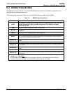
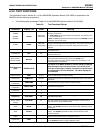
The following table supersedes Table 6-2 of the M300E/EM Operators Manual (P/N 04288).
Table 6-1: M300EU Operating Modes
MODE MEANING
A-REF
The analyzer is currently recording values for CO MEAS and CO ref, while the
sample gas stream is being routed through the CO scrubber of the auto-
reference gas path.
DIAG
One of the analyzer’s diagnostic modes is being utilized.
M-P CAL
This is the basic, multi-point calibration mode of the instrument and is activated by pressing
the CAL key.
SAMPLE
Sampling normally, flashing indicates adaptive filter is on.
SAMPLE A Indicates that unit is in SAMPLE Mode and AUTOCAL feature is activated.
SETUP
1
SETUP mode is being used to configure the analyzer (CO sampling will continue during this
process as well as data collection and output).
SPAN CAL A
2
Unit is performing span cal procedure initiated automatically by the analyzer’s AUTOCAL
feature.
SPAN CAL M
2
Unit is performing span cal procedure initiated manually by the user.
SPAN CAL R
2
Unit is performing span cal procedure initiated remotely via the RS-232, RS-4485 or digital i/o
control inputs.
ZERO CAL A
2
Unit is performing zero cal procedure initiated automatically by the analyzer’s AUTOCAL
feature.
ZERO CAL M
2
Unit is performing zero cal procedure initiated manually by the user.
ZERO CAL R
2
Unit is performing zero cal procedure initiated remotely via the RS-232, RS-4485 or digital I/O
control inputs.
1
The revision of the Teledyne Instruments software installed in this analyzer will be displayed following the word
SETUP. E.g. “SETUP
G.5”
2
The various CAL modes allow calibration of the analyzer. Because of their importance, these modes are
described separately in Chapter 7 of the M300E/EM Operators Manual (P/N 04288).
20 05831 Rev. 01