


TROUBLESHOOTING & REPAIR M300EU
Addendum to M300E/EM Manual P/N 04288
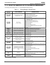
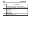
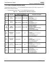
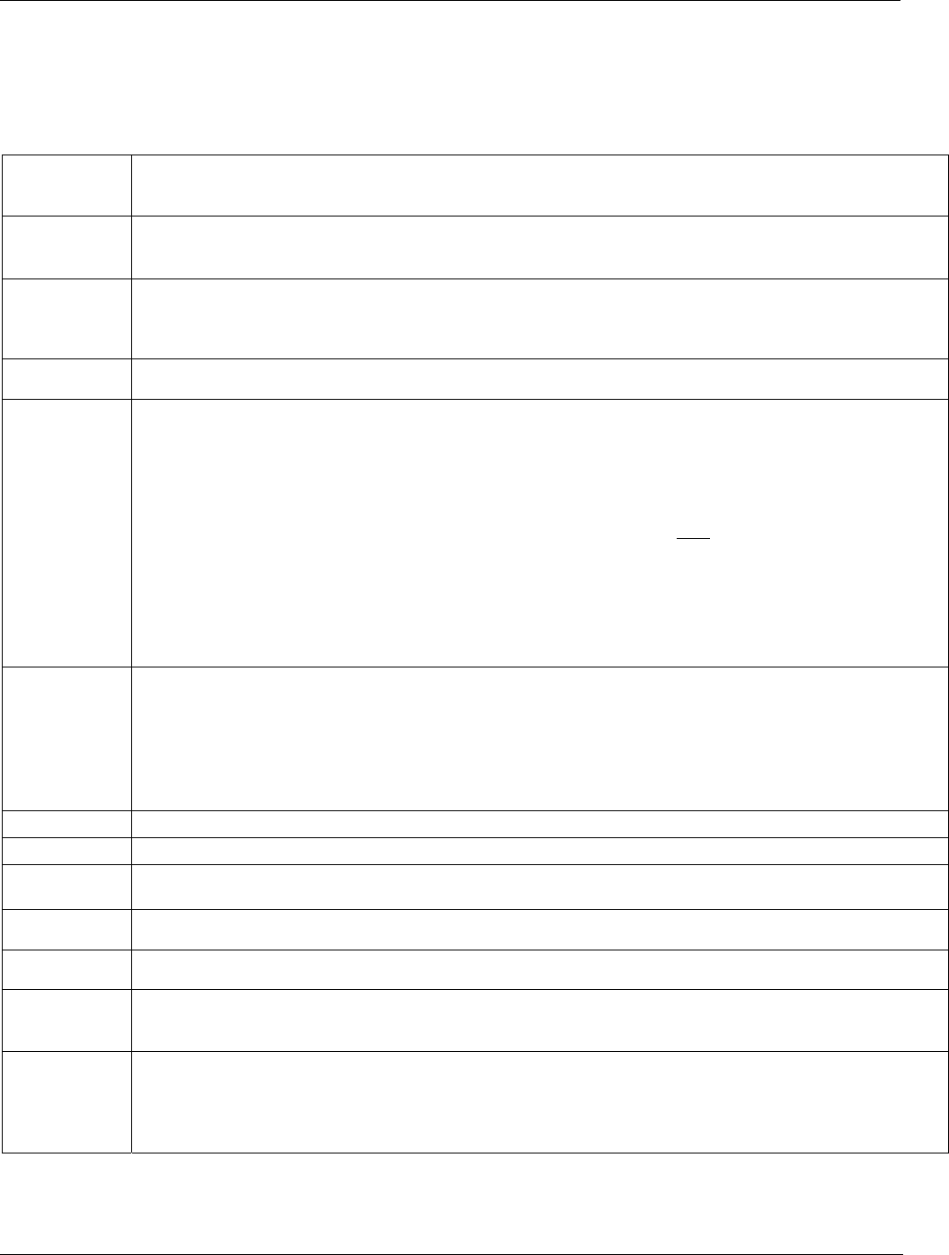
11.2.1. FAULT DIAGNOSIS WITH TEST FUNCTIONS
The following table supersedes Table 11.2 of the M300E/EM Operators Manual (P/N 04288).
Table 11-2: Test Functions - Indicated Failures
TEST
FUNCTIONS
(As Displayed)
INDICATED FAILURE(S)
TIME
Time of day clock is too fast or slow
To adjust See Section 6.6of the M300E/EM Operators Manual (P/N 04288).
Battery in clock chip on CPU board may be dead.
RANGE
Incorrectly configured measurement range(s) could cause response problems with a Data logger or chart
recorder attached to one of the analog output.
If the Range selected is too small, the recording device will over range.
If the Range is too big, the device will show minimal or no apparent change in readings.
STABIL
Indicates noise level of instrument or CO concentration of sample gas (See Section 11.4.2 of the M300E/EM
Operators Manual for causes).
CO MEAS
&
CO REF
If the value displayed is too high the IR Source has become brighter. Adjust the variable gain potentiometer on
the sync/demod board (See Section 11.6.3 of the M300E/EM Operators Manual)
If the value displayed is too low or constantly changing and the CO REF is OK:
o Failed multiplexer on the mother board
o Failed sync/demod board
o Loose connector or wiring on sync/demod board
If the value displayed is too low or constantly changing and the CO REF is
BAD:
o GFC wheel stopped or rotation is too slow
o Failed sync/demod board IR source
o Failed IR source
o Failed relay board
o Failed
I
2
C buss
o Failed IR photo-detector
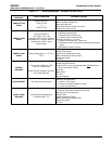
MR RATIO
When the analyzer is sampling zero air and the ratio is too low:
o The reference cell of the GFC wheel is contaminated or leaking.
o The alignment between the GFC wheel and the segment sensor, the M/R sensor or both is incorrect.
o Failed sync/demod board
When the analyzer is sampling zero air and the ratio is too high:
o Zero air is contaminated
o Failed IR photo-detector
PRES
See Table 11-1 for SAMPLE PRES WARN
SAMPLE FL
Check for gas flow problems. see Section 11.1.6 of the M300E/EM Operators Manual)
SAMPLE
TEMP
SAMPLE TEMP should be close to BENCH TEMP. Temperatures outside of the specified range or oscillating
temperatures are cause for concern
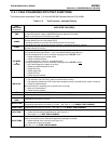
BENCH TEMP
Bench temp control improves instrument noise, stability and drift. Temperatures outside of the specified range
or oscillating temperatures are cause for concern. See Table 11-1 for BENCH TEMP WARNING
WHEEL TEMP
Wheel temp control improves instrument noise, stability and drift. Outside of set point or oscillating
temperatures are causes for concern. See Table 11-1 for WHEEL TEMP WARNING
BOX TEMP
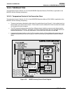
If the box temperature is out of range:
o Check the motherboard stabilization fan (see Figure 3-1).
o See Table 11-1 for BOX TEMP WARNING.
OVEN TEMP
If the oven is temperature is out of range, check both of the oven heater fans in the power supply module.
Areas to the side and rear of instrument should allow adequate ventilation.
o Check the both of the oven fans (see Figure 3-1).
o Check both of the oven heaters.
See Table 11-1 for OVEN TEMP WARNING.
(table continued)
62 05514 Rev A1