M300EU Addendum to M300E/EM Manual APPENDIX A-4: Signal I/O Definitions for 300E/EM Series Analyzers,
Rev. K.6
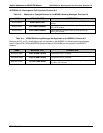
APPENDIX A-4: Signal I/O Definitions for 300E/EM Series Analyzers, Rev. K.6
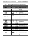
Table A-7: Additional or Changed Test Signal I/O Definitions for M300EU, Revision K.6
Signal Name
Bit or Channel
Number
Description
A status outputs, U24, J1017, pins 1–8 = bits 0–7, default I/O address 323 hex
ST_AUTO_REF
6
0 = in auto-reference mode
1 = not in auto-reference mode
ST_CONC_ALARM_2
7
0 = conc. limit 2 exceeded
1 = conc. OK
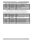
A status outputs, U24, J1017, pins 1–8 = bits 0–7, default I/O address 323 hex
ST_AUTO_REF
6
0 = in auto-reference mode
1 = not in auto-reference mode
Relay board digital output (PCF8574), default I
2
C address 44 hex
OVEN_HTR
3
0 = oven heaters on
1 = off
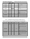
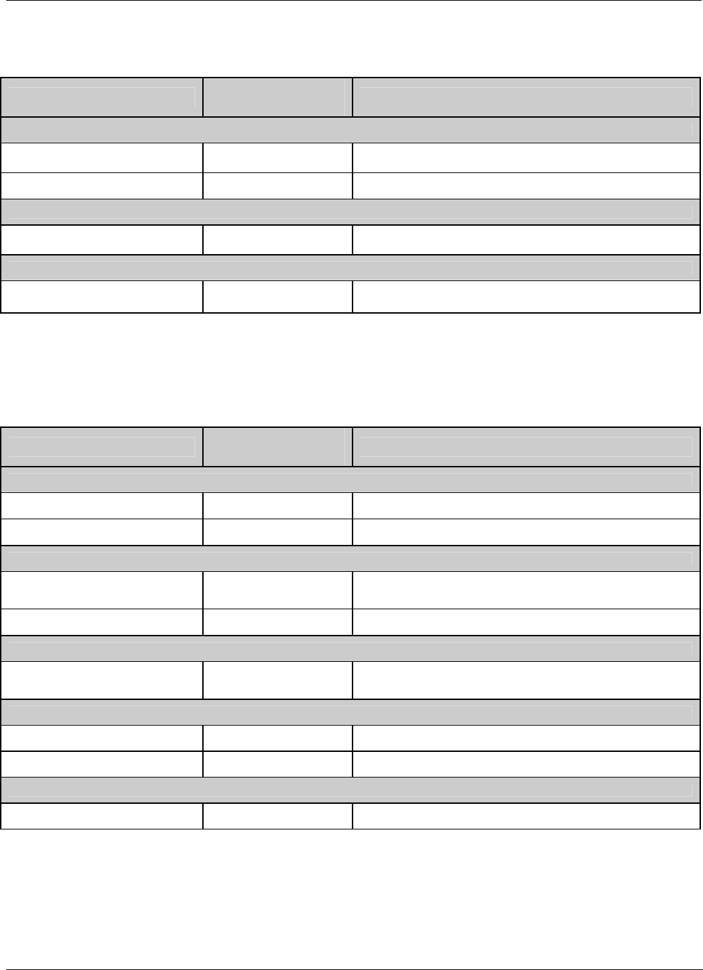
Table A-8: M300E/EM Signal I/O Definitions Not Applicable to the M300EU, Revision K.6
Because the CO
2
and O
2
sensor options are not available on the M300EU, the following signals listed in
Appendix A-4 of the M300E/EM Operators Manual (P/N 04288) are not present in the M300EU software.
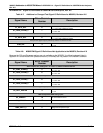
Signal Name
Bit or Channel
Number
Description
Alarm outputs, U21, J1009, pins 1–12 = bits 4–7, default I/O address 325 hex
ST_CONC_ALARM_1
5
1 = conc. limit 1 exceeded
0 = conc. OK
ST_CONC_ALARM_2
6
1 = conc. limit 2 exceeded
0 = conc. OK
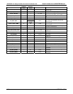
A status outputs, U24, J1017, pins 1–8 = bits 0–7, default I/O address 323 hex
ST_CONC_ALARM_1
6
0 = conc. limit 1 exceeded
1 = conc. OK
ST_CONC_ALARM_2
7
0 = conc. limit 2 exceeded
1 = conc. OK
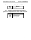
Relay board digital output (PCF8574), default I
2
C address 44 hex
O2_CELL_HEATER
5
3
0 = O
2
sensor cell heater on
1 = off
Rear board primary MUX analog inputs
O2_SENSOR
10
O
2
concentration sensor
CO2_SENSOR
12
CO
2
concentration sensor
Rear board temperature MUX analog inputs
TEMP_INPUT_5
5
Diagnostic temperature input
05924 Rev K.6 A-13


