


M300EU THEORY OF OPERATION
(Addendum to M300EU Manual - P/N 04145)
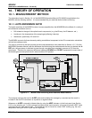
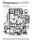
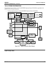
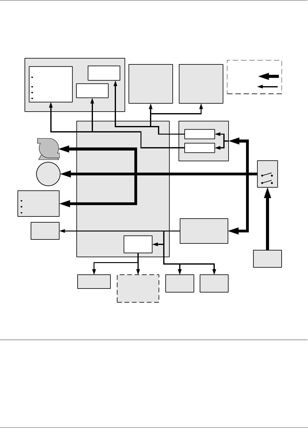
10.3.4. POWER DISTRIBUTION
The information found in Section 10.4.5 of the M300E/EM Operators Manual (P/N 04288) is applicable to the
M300EU with the following exception(s):
• This Figure replaces Figure 10-15 of the M300E/EM Operators Manual (P/N 04288).
GFC
Wheel
Motor
SENSOR SUITES
LOGIC DEVICES
(e.g. CPU, I
2
C bus,
Sync Demod PCA,
Keyboard, Display,
Motherboard, etc.)
RELAY PCA
ON / OFF
SWITCH
PS 2
(+12 VDC)
OPTIONAL
VALVES
(e.g. Sample/Cal,
Zero/Spans, etc.)
A-REF VALVE
COOLING
FAN
PUMP
AC HEATERS
Bench Heater
GFC Wheel Heater
Oven Heaters
PS 1
ANALOG SENSORS
IR detector
sensors
Temp Sensors,
Flow Sensors,
Pressure Sensors
Pre-Amplifiers
& Amplifiers
Sensor Control
& I/O Logic
Solenoid
Drivers
KEY
AC POWER
DC POWER
AC
POWER IN
+5 VDC
±15 VDC
IR Source
P/S
OVEN
FAN(S)
OPTIONAL
DEVICES
(e.g. mA Outputs,
Ethernet PCA,
Multidrop PCA, etc.)
Figure 10-8: M300EU Distribution Block Diagram
USER NOTES:
05514 Rev A1 57