


M300EU GETTING STARTED
(Addendum to M300EU Manual - P/N 04145)
3.3.2. ANALOG OUTPUT Connections
The analog outputs for the M300EU are different from those of the M300E/EM. Unlike the M300E/EM which can
include options for measuring both O
2
and CO, the M300EU is a single gas analyzer (CO) and therefore does
not require the fully configurable version of the analog outputs. The following information replaces that found in
Section 3.1.2.2 of the M300E/EM Operators Manual (P/N 04288).
The M300EU is equipped with several analog output channels accessible through a connector on the back panel
of the instrument.
• Channels A1 and A2 output a signal that is proportional to the CO concentration of the sample gas.
• The default analog output voltage setting of these channels is 0 to 5 VDC with a reporting range of 0
to 500 ppb.
• An optional Current Loop output is available for each.
• The output labeled A4 is special. It can be set by the user to output any one a variety of diagnostic test
functions.
• The default analog output voltage setting of these channels is also 0 to 5 VDC.
• See Section 6.2.2 for a list of available functions.
• There is NO optional Current Loop output is available for Channel A4.
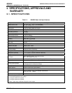
The following table lists the default settings for each of these channels.
Table 3-1: Analog Output Data Type Default Settings
PARAMETER CHANNEL DEFAULT SETTING
A1 A2 A3 A4
1
DATA TYPE
1
CONC1 CONC2
Not
Available
TEST
CHANNEL
RANGE
0 – 5 VDC
2
OVERRANGE
ON
REC OFS
0 mVDC
AUTO CAL.
ON
CALIBRATED
NO
OUTPUT
ON
1
See Table A-6 of M300E/EM Appendix A for definitions of these iDAS data types
2
Optional current loop outputs are available for analog output channels A1& A2.
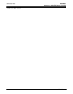
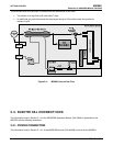
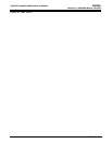
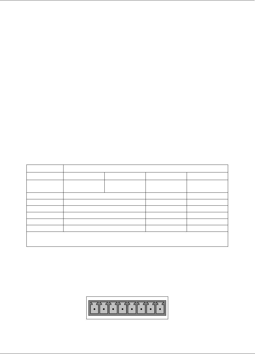
To access these signals attach a strip chart recorder and/or data-logger to the appropriate analog output
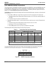
connections on the rear panel of the analyzer. Pin-outs for the analog output connector are:
ANALOG OUT
A1 A2 A3 A4
+ - + - + - + -
Figure 3-3: M300EU Analog Output Connector
05514 Rev A1 7