


TABLE OF CONTENTS M300EU
Addendum to M300E/EM Manual P/N 04288
10.3. Electronic Operation.....................................................................................................................................................53
10.3.1. Overview...............................................................................................................................................................53
10.3.2. The Relay PCA.....................................................................................................................................................54
10.3.2.1. Temperature Control of the Convection Oven...............................................................................................54
10.3.2.2. Oven Heaters AC Power Configuration ........................................................................................................55
10.3.2.3. Status LED’s .................................................................................................................................................56
10.3.3. Motherboard .........................................................................................................................................................56
10.3.3.1. A to D Conversion.........................................................................................................................................56
10.3.3.2. Sensor Inputs................................................................................................................................................56
10.3.4. Power Distribution.................................................................................................................................................57
11. TROUBLESHOOTING & REPAIR .....................................................................................................................................59
11.1. General Notes ..............................................................................................................................................................59
11.2. Fault Diagnosis with Warning Messages......................................................................................................................60
11.2.1. Fault Diagnosis with Test Functions .....................................................................................................................62
11.2.2. Relay Board Status LED’s ....................................................................................................................................64
11.3. Gas flow problems........................................................................................................................................................65
11.4. Other Performance Problems.......................................................................................................................................65
11.4.1. Unexplained drift...................................................................................................................................................65
11.5. Subsystem Chechout ...................................................................................................................................................66
11.5.1. Relay Board..........................................................................................................................................................66
11.5.2. Motherboard .........................................................................................................................................................66
11.5.2.1. A/D Functions ...............................................................................................................................................66
11.6. Technical Assistance....................................................................................................................................................67
LIST OF FIGURES
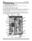
Figure 3-1: M300EU Internal Layout................................................................................................................5
Figure 3-2: M300EU Internal Gas Flow............................................................................................................6
Figure 3-3: M300EU Analog Output Connector...............................................................................................7
Figure 5-1: M300EU Internal Pneumatic Flow– Zero/Span Valves with Zero Scrubber (OPT 50A) .............16
Figure 5-2: M300EU Internal Pneumatic Flow– Zero/Span Valves with IZS (OPT 51B)...............................17
Figure 5-3: M300EU Internal Pneumatic Flow– Zero/Span Valves with IZS & Shutoff Valve (OPT 51C).....18
Figure 6-1: Typical Front Panel Display during A-REF Mode........................................................................21
Figure 6-2: Analog Output Connector Pin Out ...............................................................................................23
Figure 10-1: M300EU Gas flow during Auto-Reference Measurements..........................................................49
Figure 10-2: Auto-Reference Measurement Cycle...........................................................................................50
Figure 10-3: Semi-Permeable Membrane Drying Process ..............................................................................51
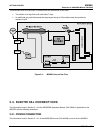
Figure 10-4: M300EU Electronic Overview Block Diagram .............................................................................53
Figure 10-5: M300EU Heating Control Block Diagram ....................................................................................54
Figure 10-6: M300EU Oven Heater Configuration Jumpers............................................................................55
Figure 10-7: M300EU Oven Heater Configuration Circuit................................................................................55
Figure 10-8: M300EU Distribution Block Diagram ...........................................................................................57
LIST OF TABLES
Table 2-1: M300EU Basic Unit Specifications ................................................................................................3
Table 3-1: Analog Output Data Type Default Settings....................................................................................7
Table 3-2: Analog Output Pin Outs.................................................................................................................8
Table 3-3: Status Output Pin Assignments.....................................................................................................8
Table 3-4: Possible Warning Messages at Start-Up.......................................................................................9
Table 5-1: Possible Warning Messages at Start-Up.....................................................................................15
Table 6-1: M300EU Operating Modes ..........................................................................................................20
Table 6-2: Test Functions Defined................................................................................................................22
Table 6-3: Test Functions Defined................................................................................................................32
Table 6-4: M300EU Diagnostic (DIAG) Submenus.......................................................................................33
Table 6-5: DIAG - Analog I/O Functions .......................................................................................................34
Table 6-6: Test Channels Functions Available on the M300EU’s Analog Output ........................................38
ii 05904 Rev A