M300EU THEORY OF OPERATION
(Addendum to M300EU Manual - P/N 04145)
10. THEORY OF OPERATION
10.1. MEASUREMENT METHOD
The information found in Section 10.1 of the M300E/EM Operators Manual (P/N 04288) is applicable to the
M300EU with the following addition. It is recommended that you read that section before continuing.
10.1.1. AUTO-REFERENCE RATIO
The higher resolution of the M300EU makes it more susceptible then the M300E/EM to the effects of a variety of
environmental conditions such as:
• Drift related to the age of the optical bench components ( e.g. the IR lamp, the IR detector, etc.)
• Variations in the temperature of the sample gas (affecting it density).
• Interferents, specifically CO
2
and H
2
O.
The M300EU accounts for these issues by adding an additional component to the CO concentration calculation
call the Auto-reference ratio.
This ratio is arrived at in the same manner as the measure/reference ratio (described in Section 10.1.3.2 of the
M300E/EM Operators Manual) with the difference that that during the measurements that are to calculate the A-
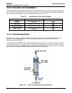
REF ratio, the gas stream is switched to pass through a scrubber that completely removes all CO from the
sample gas. Therefore the measured difference between CO MEAS and CO REF represents the exact state of
the sample gas and the optical bench’s sensors without CO present.
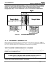
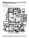
Figure 10-1: M300EU Gas flow during Auto-Reference Measurements
The analyzer averages the last five A-REF ratios and multiplies this average by a constant and the result is
included in the final CO calculation as a positive or negative offset.
Whenever an A-REF is manually initiated either by using the AREF submenu via the front panel (see Section
6.4.2) or by activating pin-7 of the instrument’s digital control input connector, all previously stored A-REF ratios
are erased and the new ratio inserted. This allows the user to correct for a bad A-REF reading (e.g. the oven
temperature during the A-REF cycle was too high/low)
05514 Rev A1 49


